
In the Construction Stages Analysis (CSA) add-on, you can use built-up cross-sections by means of what are known as phase sections. This allows you to activate and deactivate the parts of the "Parametric - Massive II" section type throughout the construction stages.

In the Steel Joint add-on, you can design the connections of members with composite cross-sections. Furthermore, you can perform joint design checks for almost all thin-walled cross-sections in the RFEM library.
Go to Explanatory Video
- A wide range of cross-sections, such as rectangular sections, square sections, T‑sections, circular sections, built-up cross-sections, irregular parametric cross-sections, and many others (suitability for design depends on the selected standard)
- Design of cross-laminated timber (CLT)
- Design of timber-based materials and laminated veneer lumber according to EC 5
- Design of tapered and curved members (design method according to the standard)
- Adjustment of the essential design factors and standard parameters is possible
- Flexibility due to detailed setting options for basis and extent of calculations
- Fast and clear results output for an immediate overview of the result distribution after the design
- Detailed output of the design results and essential formulas (comprehensible and verifiable result path)
- Numerical results clearly arranged in tables and graphical display of the results in the model
- Integration of the output into the RFEM/RSTAB printout report

- Many predefined components: Allow easy input of typical connection situations, such as end plates, angles, multi-wall sheets, cleats, fin plates
- Universally applicable basic components (plates, welds, bolts, auxiliary planes) for entering complex connection situations
- Graphical display of the connection geometry that is updated in parallel with the input
- The Steel Joints Template included in the add-on allows you to select from several connection types and, and once selected, it will be applied to your model.
- Wide range of cross-section shapes: Includes I-sections, channel sections, angles, T-sections, built-up cross-sections, RHS (rectangular hollow sections), and thin-walled sections
- The Template covers connections from three general categories: Rigid, Pinned, Truss
- Automatic adaptation of the connection geometry, even if the structural components are subsequently edited, based on the relative relation of the components
_(1).png?mw=640&hash=415f7bbaf70e41679bb0106e1cf91eaa8c493ec9)
- Automatic generation of FE analysis models: The add-on automatically creates a finite element model (FE) of the steel connection in the background.
- Consideration of all internal forces: The calculation and design checks include all internal forces (N, Vy, Vz, My, Mz, MT) and are not limited to planar loading.
- Automatic load transfer: All load combinations are automatically transferred to the FE analysis model of the connection. The loads are transferred directly from RFEM, so manual data input is not necessary.
- Efficient modeling: The add-on saves you time when modeling complex connection situations. You can also save the created FE analysis model and use it further for your own detailed analyses.
- Extensible library: An extensive and extensible library with predefined steel connection templates is available.
- Wide applicability: The add-on is suitable for connections of any type and shape, compatible with almost all rolled, welded, built-up, and thin-walled cross-sections.
- A wide range of available sections, such as rolled I-sections; channel sections; T-sections; angles; rectangular and circular hollow sections; round bars; symmetrical and asymmetrical, parametric I-, T-, and angle sections; built-up cross-sections (suitability for design depends on the selected standard)
- Design of general RSECTION cross-sections (depending on the design formats available in the respective standard); for example, equivalent stress design
- Design of tapered members (design method depending on the standard)
- Adjustment of the essential design factors and standard parameters is possible
- Flexibility due to detailed setting options for basis and extent of calculations
- Fast and clear results output for an immediate overview of the result distribution after the design
- Detailed output of the design results and essential formulas (comprehensible and verifiable result path)
- Numerical results clearly arranged in tables and graphical display of the results in the model
- Integration of the output into the RFEM/RSTAB printout report

SHAPE-THIN determines the section properties and stresses of any open, closed, built-up, or non-connected cross-sections.
- Section Properties
- Cross-sectional area A
- Shear areas Ay, Az, Au, and Av
- Centroid position yS, zS
- moments of area 2 degrees Iy, Iz, Iyz, Iu, Iv, Ip, Ip,M
- Radii of gyration iy, iz, iyz, iu, iv, ip, ip,M
- Inclination of principal axes α
- Cross-section weight G
- Cross-section perimeter U
- torsional constants of area degrees IT, IT,St.Venant, IT,Bredt, IT,s
- Location of the shear center yM, zM
- Warping constants Iω,S, Iω,M or Iω,D for lateral restraint
- Max/min section moduli Sy, Sz, Su, Sv, Sω,M with locations
- Section ranges ru, rv, rM,u, rM,v
- Reduction factor λM
- Plastic Cross-Section Properties
- Axial force Npl,d
- Shear forces Vpl,y,d, Vpl,z,d, Vpl,u,d, Vpl,v,d
- Bending moments Mpl,y,d, Mpl,z,d, Mpl,u,d, Mpl,v,d
- Section moduli Zy, Zz, Zu, Zv
- Shear areas Apl,y, Apl,z, Apl,u, Apl,v
- Position of area bisecting axes fu, fv,
- Display of the inertia ellipse
- First moments of area Qu, Qv, Qy, Qz with location of maxima and specification of shear flow
- Warping coordinates ωM
- moments of area (warping areas) Sω,M
- Cell areas Am of closed cross-sections
- Normal stresses σx due to axial force, bending moments, and warping bimoment
- Shear stresses τ from shear forces as well as primary and secondary torsional moments
- Equivalent stresses σv with customizable factor for shear stresses
- Stress ratios, related to limit stresses
- Stresses for element edges or center lines
- Weld stresses in fillet welds
- Section properties of non-connected cross-sections (cores of high-rise buildings, composite sections)
- Shear wall shear forces due to bending and torsion
- Plastic capacity design with determination of the enlargement factor αpl
- Check of the c/t-ratios following the design methods el-el, el-pl or pl-pl according to DIN 18800
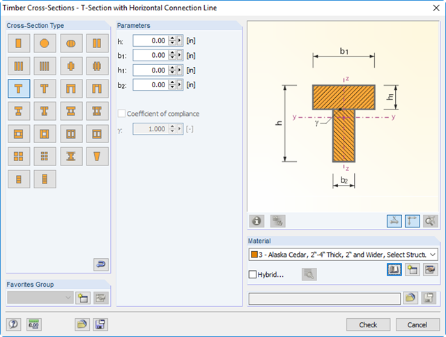
You can define built-up timber cross-sections, for example, channel, T, I, and box girders. Single elements are connected by rigid or semi‑rigid connections. Furthermore, hybrid cross-sections are available. In this case, a submenu provides an option to assign different materials to the individual cross‑section parts.