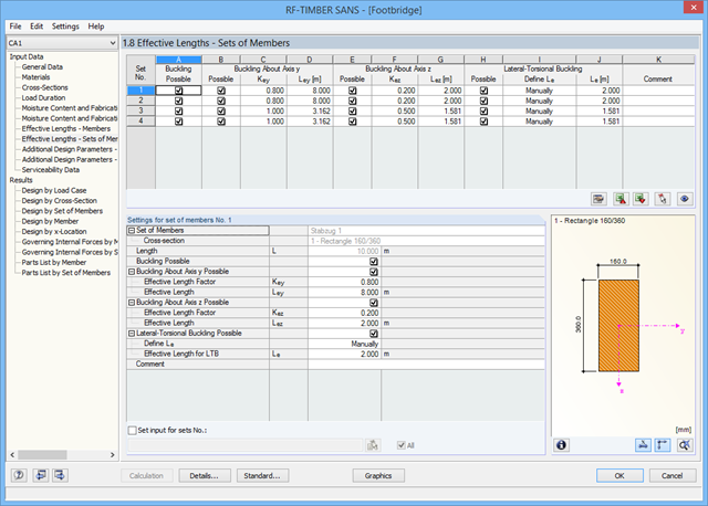
The design analyzes tension and compression along the grain, bending, bending and tension or compression, and shear due to shear force with and without torsion. Designs proceed at the level of design stress values. The design of structural components at risk of buckling or lateral buckling is performed according to the Equivalent Member Method and considers the systematic axial compression, bending with and without compression force as well as bending and tension.
The deflection in the characteristic and quasi-permanent design situations is determined for inner spans and cantilevers. Separate design cases allow for a flexible analysis of specific actions as well as for individual stability analyses. You can define the design type to be performed in the Control Parameters window.
The cross-section resistance design analyzes tension and compression along the grain, bending, bending and tension/compression as well as the strength in shear due to shear force.
The design of structural components at risk of buckling or lateral buckling is performed according to the Equivalent Member Method and considers the systematic axial compression, bending with and without compression force as well as bending and tension. The deflection of inner spans and cantilevers is compared to the maximum allowable deflection.
Separate design cases allow for a flexible and stability analysis of members, sets of members, and loads.
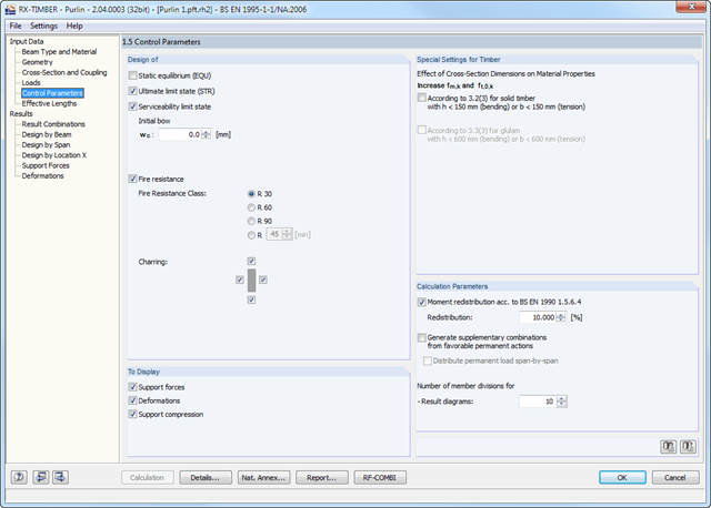
Design-relevant parameters such as load duration in case of fire, member slendernesses, limit deflection can be adjusted as desired.
The design analyzes tension and compression along the grain, bending, bending and tension or compression, and shear due to shear force with and without torsion. Designs proceed at the level of design stress values.
The design of structural components at risk of buckling or lateral buckling is performed according to the Equivalent Member Method and considers the systematic axial compression, bending with and without compression force as well as bending and tension. The deflection of inner spans and cantilevers is determined in characteristic and quasi-permanent design situations.
Separate design cases allow for a flexible and stability analysis of members, sets of members, and loads. In the case of tapered members, the cut-to-grain angle is considered in the bending tension and bending compression area. If there is a ridge defined, the module performs the ridge design additionally.
The cross-section resistance design analyzes tension and compression along the grain, bending, bending and tension/compression as well as the strength in shear due to shear force.
The design of structural components at risk of buckling or lateral buckling is performed according to the Equivalent Member Method and considers the systematic axial compression, bending with and without compression force as well as bending and tension. The deflection of inner spans and cantilevers is compared to the maximum allowable deflection.
Separate design cases allow for a flexible and stability analysis of members, sets of members, and loads.
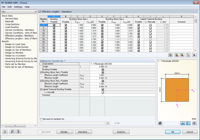
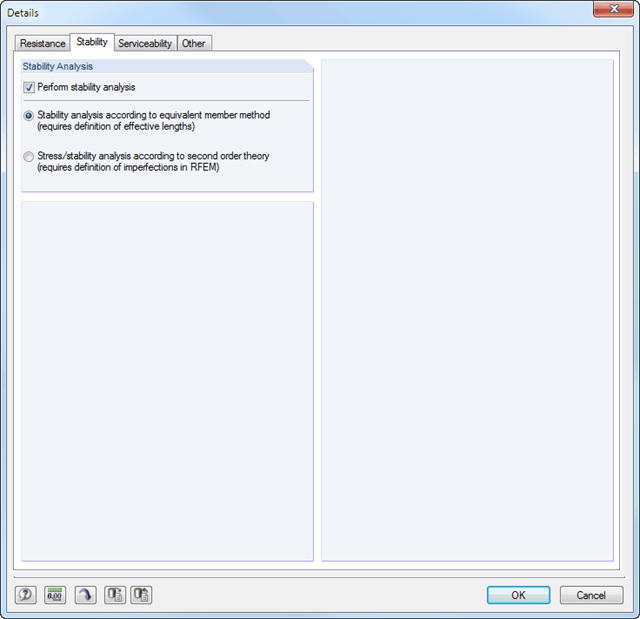
Design-relevant parameters such as the stability analysis type, member slendernesses, and limit deflections, can be freely adjusted.
The cross-section resistance design analyzes tension and compression along the grain, bending, bending and tension/compression as well as the strength in shear due to shear force.
The design of structural components at risk of buckling or lateral buckling is performed according to the Equivalent Member Method and considers the systematic axial compression, bending with and without compression force as well as bending and tension. Deflection of inner spans and cantilevers is compared with the maximum allowable deflection.
Separate design cases allow a flexible analysis for selected members, sets of members, and actions, as well as for the individual stability analyses. such as stability analysis, load duration in case of fire, member slendernesses, and limit deflection can be adjusted as desired.
The cross-section resistance design analyzes tension and compression along the grain, bending, bending and tension/compression as well as the strength in shear due to shear force.
The design of structural components at risk of buckling or lateral buckling is performed according to the Equivalent Member Method and considers the systematic axial compression, bending with and without compression force as well as bending and tension. The deflection of inner spans and cantilevers is compared to the maximum allowable deflection.
Separate design cases allow for a flexible and stability analysis of members, sets of members, and loads.
Design-relevant parameters such as such as stability analysis, load duration in case of fire, member slendernesses, and limit deflection can be adjusted as desired.
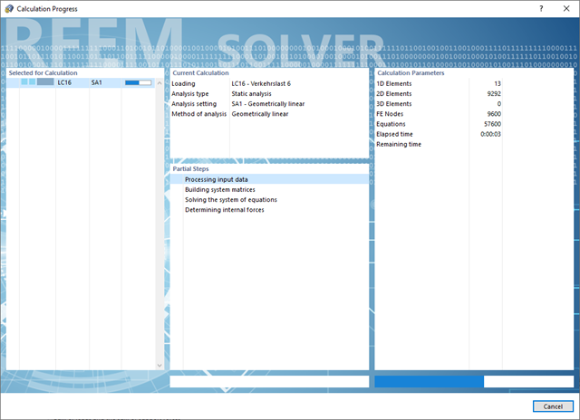
Convince yourself by the powerful calculation kernel, its optimized networking and support of multi-core processor technology. This provides you with the advantages, such as parallel calculations of linear load cases and load combinations using several processors without additional demands on the RAM. The stiffness matrix only has to be created once. Thus, you can calculate even large systems with the fast direct solver.
If you need to calculate multiple load combinations in your models, the program initiates several solvers in parallel (one per core). Each solver then calculates a load combination, which improves the core utilization.
You can systematically follow the development of the deformation displayed in a diagram during the calculation, and thus precisely evaluate the convergence behavior.
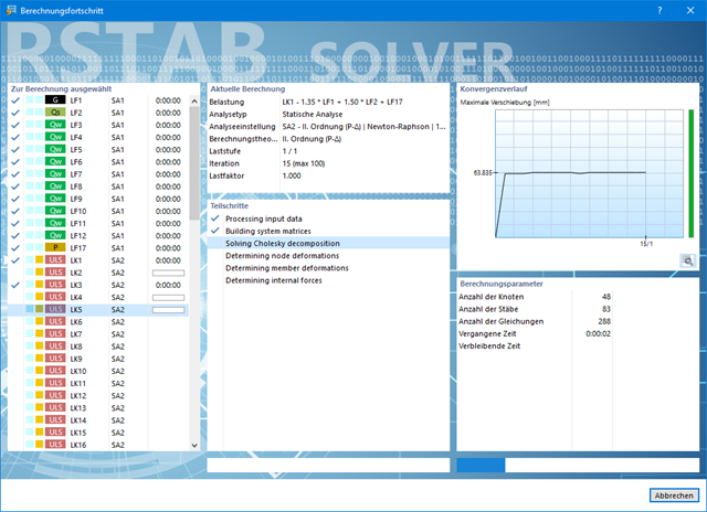
Also in this case, RSTAB will certainly convince you. With the powerful calculation kernel, its optimized networking and support of multi-core processor technology, the Dlubal structural analysis program is far ahead. This allows you to calculate more linear load cases and load combinations using several processors in parallel without using additional memory. The stiffness matrix only has to be created once. Thus, it is possible for you to calculate even large systems with the fast and direct solver.
Do you have to calculate multiple load combinations in your models? The program initiates several solvers in parallel (one per core). Each solver then calculates a load combination for you. This leads to better utilization of the cores.
You can systematically follow the development of the deformation displayed in a diagram during the calculation, and thus precisely evaluate the convergence behavior.