- Full integration in RFEM/RSTAB with import of relevant internal forces
- Design checks for the elastic-elastic and elastic-plastic methods
- Graphical selection of members and sets of members for design
- Analysis for several load and design cases
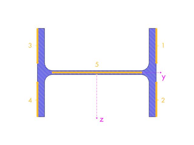
- Design based on the buckling field parameters integrated in the cross-section library for the cross-section parts supported on one and both sides
- Optional determination of shear stresses according to comment on El. (745)
- Possibility to consider the weld thickness in the design of welded cross-sections, which has the effect of a shortening of the cross-section part width
- Cross-section optimization with the option to export modified cross-sections

In RFEM and RSTAB, you can visualize the flow field quantities of pressure, velocity, turbulence kinetic energy, and turbulence dissipation rate for the wind simulation.
The clipping planes are aligned with the respective wind direction.
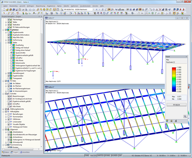
After the design, the results are displayed in different windows sorted by cross-sections, members, sets of members, or x-locations. The corresponding cross-section graphic is always displayed with the result values in tables. In RFEM/RSTAB, they are highlighted by different colors in the structural model. Critical or oversized components can be identified at a glance. You can modify the colors and values assigned.
Result diagrams of a member or a set of members ensure targeted evaluation. It is also possible to represent all intermediate values.
The masses determined during the design are displayed in parts lists for both members and sets of members.
Furthermore, you can export all result tables to MS Excel or in a CSV file. A special transfer menu defines all specifications required for the export.
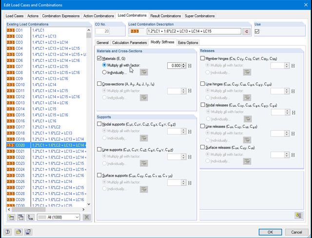
Do not lose track of stiffnesses and initial deformations. In the individual load cases or combinations, you have the option to modify the stiffnesses of materials, cross-sections, nodal, line and surface supports, and member and line hinges for all or selected members. You can also consider initial deformations from other load cases or load combinations.
- Automatic import of internal forces from RFEM/RSTAB
- Optional consideration of creep
- Automatic determination of planned and unintentional eccentricity from the second-order analysis in addition to the existing eccentricity
- Determination of internal forces according to the linear static analysis and the second-order analysis
- Analysis of governing design locations along the column due to existing loading
- Output of the required longitudinal and stirrup reinforcement
- Summary of design ratios, including all design details

- Import of relevant information and results from RFEM
- Integrated, editable material and section library
- Sensible and complete presetting of input parameters
- Punching design on columns (all section shapes), wall ends, and wall corners
- Automatic recognition of the punching node position from an RFEM model
- Detection of curves or splines as a boundary of the control perimeter
- Automatic consideration of all slab openings defined in the RFEM model
- Construction and graphical display of the control perimeter
- Optional design with unsmoothed shear stress along the control perimeter that corresponds to the actual shear stress distribution in the FE model
- Determination of the load increment factor β via full-plastic shear distribution as constant factors according to EN 1992‑1‑1, Sect. 6.4.3 (3), based on EN 1992‑1‑1, Fig. 6.21N, or by a user‑defined specification
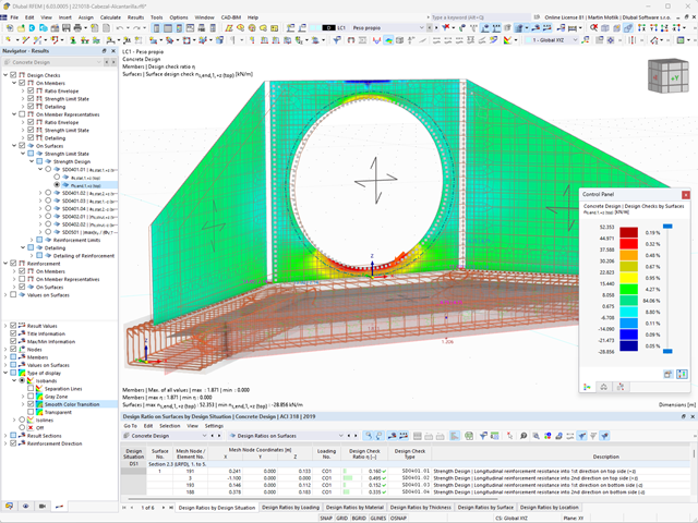
- Numerical and graphical display of results (3D, 2D, and in sections)
- Punching design of the slab without punching reinforcement
- Qualitative determination of the required punching reinforcement
- Design and analysis of the longitudinal reinforcement
- Complete integration of results in an RFEM printout report
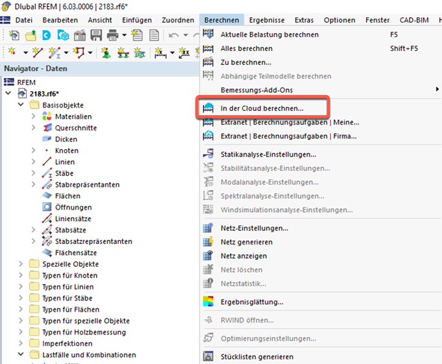
- Outsource calculation on a computing server in the cloud
- Option to select different powerful computing servers
- Clearly arranged display of all calculation tasks in the Extranet
- Calculated files are available for download for two months
- Virtually unlimited computing capacity using cloud technology
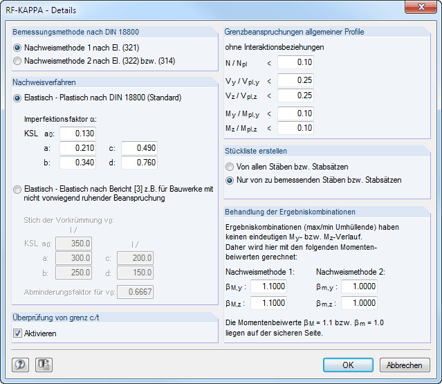
In a separate dialog box, you can specify extensive detailed settings for the design:
Design Method According to DIN 18800
- Design Method 1 According to El. (321)
- Design Method 2 According to El. (322)
Analysis method
- Elastic-Plastic according to DIN 18800
- Elastic-elastic according to a publication by Kretschmar, J./Österrieder, P./beirow, B.
Limit loading of general sections
- General sections – these include all cross-sections that cannot be assigned to single or double symmetric I-sections, box sections, or pipe sections – can also be designed according to the equivalent member method against flexural buckling. In this case, however, the plastic cross-section properties are determined without interaction conditions. The allowable application limits for this consideration depend on the ratio of the existing internal force to the fully plastic internal force. Five text boxes provide the option for user-defined control.
Check of limit (c/t)
- In this dialog section, you can activate or deactivate the check of c/t ratios.
Treatment of Result Combinations
- When designing a result combination, a result set is obtained due to the result superposition on each member location, which makes it impossible to clearly determine the moment factors. In this section, you can thus freely specify a global moment factor for a result combination design. The predefined values are on the safe side, regardless of the design method.
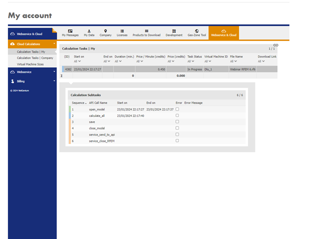
After completing the calculation, you will receive an email with a link to download the calculated file. Large files are compressed into a ZIP archive. Smaller files can be downloaded directly.
As an alternative, there is a link to the calculated file in the Extranet.
The downloaded file is a common RFEM file and can be used for further processing as usual.

- Analysis of time diagrams and accelerograms (acceleration-time diagrams exciting the supports of a structure)
- Combination of user-defined time diagrams with nodal, member, and surface loads, as well as free and generated loads
- Combination of several independent excitation functions
- Linear implicit Newmark analysis or modal analysis in time history
- Structural damping using Raleigh damping coefficients or Lehr's damping value
- Graphical display of results in calculation diagrams
- Result display in individual time steps or as an envelope during the entire time period
- Extensive library of seismic events (accelerograms)