8 Results
View Results:
Sort by:

Reinforced concrete usually answers the question "How much can you carry?" simply with "Yes". Nevertheless, you need a three-dimensional moment-moment-axial force interaction diagram for the graphical output of the ultimate limit state of reinforced concrete cross-sections. The Dlubal structural analysis software offers you just that.
With the additional display of the load action, you can easily recognize or visualize whether the limit resistance of a reinforced concrete cross-section is exceeded. Since you can control the diagram properties, you can customize the appearance of the My-Mz-N diagram to suit your needs.
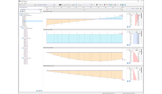
Customize the display of your data to your individual preferences. The result diagrams of members, surfaces (RFEM), and supports are freely configurable. You can define smooth ranges with average values or, if necessary, display and hide the result distributions. This ensures targeted evaluation of your results. Furthermore, you can easily add all diagrams to the printout report.
If you are interested in making your daily work easier and more efficient, you should also pay attention to this feature. Program configuration menus and toolbars can be freely customized. This allows you to arrange your frequently used functions in a user-defined way and save time. Everything from the beginning? No problem: You can restore the default settings of the program with a mouse click. Tables, navigators, and toolbars can also be moved and docked as required.
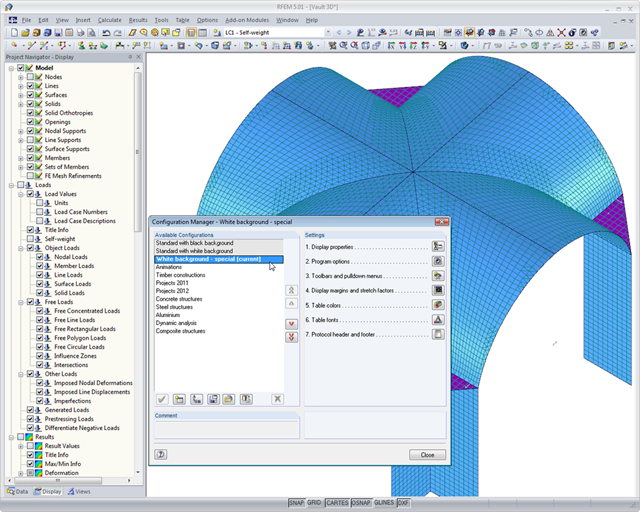
Furthermore, you can use the configuration manager to set the graphic display properties, toolbars, and so on in a user-defined way and save them as your own configuration. Thus, the software becomes your individual productivity enhancer.
Dlubal Software customers come from all over the world and there are, of course, numerous language options for the structural analysis software. It is possible to operate the program in the following languages: English, Chinese, Czech, Dutch, French, German, Italian, Polish, Portuguese, Russian, and Spanish.
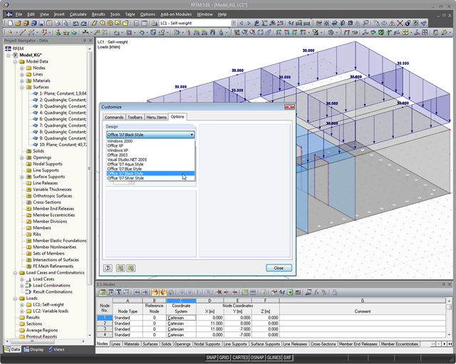
You can also modify the design of the RFEM/RSTAB user interface: There are nine different styles of graphical user interface to choose from; for example: Office 2007 Blue, Silver, Aqua, and Black. Customize the programs to your individual needs.
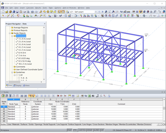
Customize your model to work even more efficiently. You can selectively display or hide various objects, such as nodes, members, supports, and others. The model can be dimensioned by using lines, arcs, inclinations, or height nodes. Freely createable guidelines, sections, and comments facilitate you the input and evaluation. You can also display or hide the guide objects individually.
- Structure generator for typical geometries with loading and combinations
- Importing and exporting data from spreadsheet programs such as MS Excel and MS Access
- Connection to various programs compatible with COM, for example, B. CAD systems
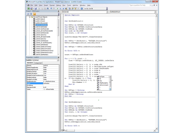
- Customized pre- and postprocessing modules
- Processing and results of data in user-defined formats
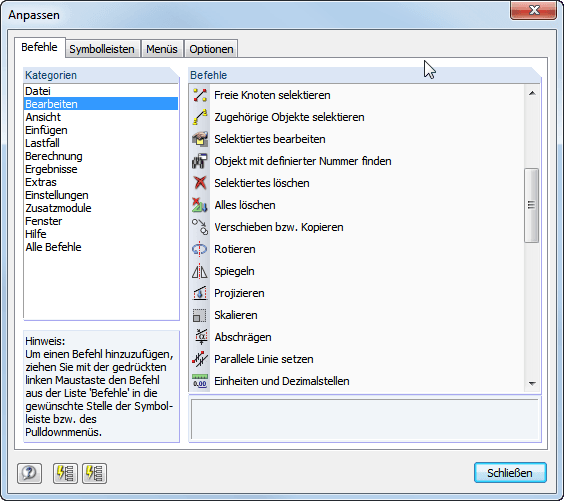
Program configuration menus and toolbars can be freely customized. It is possible to setup an arrangement of frequently used functions and tools for quick access. Tables, navigators, and toolbars can also be freely moved and docked. The default settings of the program can be restored at the click of a button.
In addition, it is possible in the Configuration Manager to set the graphic display properties, toolbars, and so on in a user-defined way and save them as your own configuration.
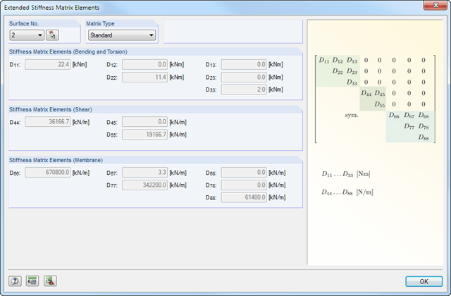
It is necessary to select load cases, load combinations, and result combinations for the ultimate and the serviceability limit state design. After selecting the surfaces to be designed, you can define the relevant material model.
The structure of layers forming the basis for the stiffness calculation can vary. You can adjust the parameters defined by the selected material model according to your individual needs. The 3*3 matrix of the layers is modifiable as well. In this way completely free selection when generating the stiffnesses is provided.
The limit stresses of each layer are defined by the selected material. These values can be customized as well.