3 Wyniki
Wyświetl wyniki:
Sortuj według:
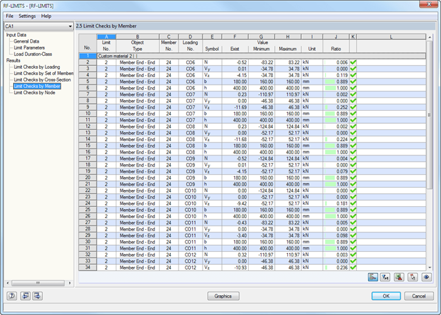
Najpierw wyświetlane są decydujące obliczenia połączenia dla danego przypadku obciążenia oraz kombinacji obciążeń lub kombinacji wyników. Ponadto możliwe jest oddzielne wyświetlanie wyników dla zbiorów prętów, przekrojów, prętów, węzłów i podpór węzłowych.
- Możesz użyć filtra, aby jeszcze bardziej zredukować wyświetlane wyniki, a tym samym przedstawić je w bardziej przejrzysty sposób.
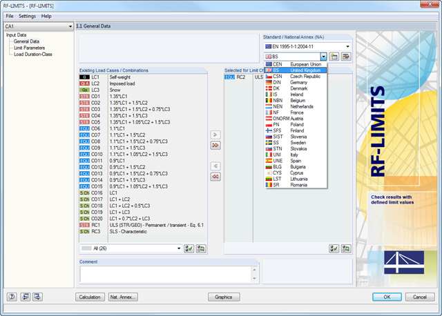
Po wybraniu obciążeń wymaganych do obliczeń oraz, w razie potrzeby, żądanej normy do obliczeń, w oknie 1.2 Parametry graniczne można zdefiniować obciążenia graniczne. Możliwe jest dodawanie innych producentów do listy w bazie danych.
Po wybraniu wszystkich elementów granicznych do obliczeń można opcjonalnie zdefiniować klasę trwania obciążenia (KTO). Trzecie okno modułu jest dostępne jedynie w przypadku wymiarowania elementów połączeń drewnianych wg EN 1995-1-1 lub DIN 1052.
- Wymiarowanie końców, prętów, podpór węzłowych, węzłów i powierzchni
- Uwzględnienie określonych obszarów obliczeniowych
- Kontrola wymiarów przekroju
- Wymiarowanie według EN 1995-1-1 (Europejska norma dotycząca drewna) zgodnie z odpowiednimi załącznikami krajowymi + DIN 1052 + DSTV DIN EN 1993-1-8 + ANSI/AWC - NDS 2015 (norma amerykańska)
- Projektowanie różnych materiałów, takich jak stal, beton i inne
- Nie ma konieczności łączenia się z konkretnymi normami
- Rozszerzalna biblioteka o elementy łaczące z drewna (SIHGA, Sherpa, WÜRTH, Simpson StrongTie, KNAPP, PITZL) i elementy stalowe (połączenia znormalizowane w konstrukcjach stalowych zgodnie z EC 3, M-connect, PFEIFER, TG-Technik)
- Nośności graniczne belek drewnianych firm STEICO i Metsä Wood dostępne w bibliotece
- Połączenie z MS Excel
- Optymalizacja elementów łączących (obliczany jest element najczęściej wykorzystywany)