54 Wyniki
Wyświetl wyniki:
Sortuj według:

W rozszerzeniu Połączenia stalowe można używać nie tylko zwykłych typów prętów 'Belka', 'Kratownica' itd., ale także typu pręta 'Belka wynikowa' oraz przekroje z elementów powierzchniowych. Należy wybrać odpowiedni przekrój dla belki wynikowej, a następnie zdefiniować otwory prętowe w modelu powierzchniowym za pomocą edytora prętów.

W rozszerzeniu Połączenie stalowe można rozmieszczać obiekty w odniesieniu do innych obiektów.

Komponent 'Kontakt powierzchniowy' w rozszerzeniu Połączenia stalowe umożliwia uwzględnienie kontaktu ciśnieniowego między dwiema równoległymi płytami/płytami prętowymi. W takim przypadku można opcjonalnie uwzględnić tarcie między powierzchniami

Komponent "Stub" jest dostępny w rozszerzeniu Połączenia stalowe. Umożliwia ona wydłużenie pręta za pomocą połączenia płatwi z innym prętem (krótkiem) i połączenie go z komponentem odniesienia.

W rozszerzeniu Połączenia stalowe można teraz układać płyty w różne kształty geometryczne. Oprócz „Prostokąta” i „Okręgu” dostępny jest nowy kształt „Wielokąt”. Forma wielokąta jest określana przez zdefiniowaną współrzędną punktu.

W konfiguracji granicznej dla wymiarowania połączenia stalowego istnieje możliwość modyfikacji granicznego odkształcenia plastycznego dla spoin.

Parametry załączników krajowych (NA) do Eurokodu 3 z następujących krajów są zintegrowane:
-
 DIN EN 1993-1-1/NA:2016-04 (Niemcy)
 -
 ÖNORM EN 1993-1-1/NA:2015-12 (Austria)
 -
 SN EN 1993-1-1/NA:2016-07 (Szwajcaria)
 -
 BDS EN 1993-1-1/NA:2015-10 (Bułgaria)
 -
 BS EN 1993-1-1/NA:2016-07 (Wielka Brytania)
 -
 CEN EN 1993-1-1/2015-06 (Unia Europejska)
 -
 CYS EN 1993-1-1/NA:2015-07 (Cypr)
 -
 CSN EN 1993-1-1/NA:2016-06 (Republika Czeska)
 -
 DS EN 1993-1-1/NA:2015-07 (Dania)
 -
 ELOT EN 1993-1-1/NA:2017-01 (Grecja)
 -
 EVS EN 1993-1-1/NA:2015-08 (Estonia)
 -
 HRN EN 1993-1-1/NA:2016-03 (Chorwacja)
 -
 I S. EN 1993-1-1/NA:2016-03 (Irlandia)
 -
 ILNAS EN 1993-1-1/NA:2015-06 (Luksemburg)
 -
 IST EN 1993-1-1/NA:2015-11 (Islandia)
 -
 LST EN 1993-1-1/NA:2017-01 (Litwa)
 -
 LVS EN 1993-1-1/NA:2015-10 (Łotwa)
 -
 MS EN 1993-1-1/NA:2010-01 (Malezja)
 -
 MSZ EN 1993-1-1/NA:2015-11 (Węgry)
 -
 NBN EN 1993-1-1/NA:2015-07 (Belgia)
 -
 NEN EN 1993-1-1/NA:2016-12 (Holandia)
 -
 NF EN 1993-1-1/NA:2016-02 (Francja)
 -
 NP EN 1993-1-1/NA:2009-03 (Portugalia)
 -
 NS EN 1993-1-1/NA:2015-09 (Norwegia)
 -
 PN EN 1993-1-1/NA:2015-08 (Polska)
 -
 SFS EN 1993-1-1/NA:2015-08 (Finlandia)
 -
 SIST EN 1993-1-1/NA:2016-09 (Słowenia)
 -
 SR EN 1993-1-1/NA:2016-04 (Rumunia)
 -
 SS EN 1993-1-1/NA:2019-05 (Singapur)
 -
 SS EN 1993-1-1/NA:2015-06 (Szwecja)
 -
 STN EN 1993-1-1/NA:2015-10 (Słowacja)
 -
 TKP EN 1993-1-1/NA:2015-04 (Białoruś)
 -
 UNE EN 1993-1-1/NA:2016-02 (Hiszpania)
 -
 UNI EN 1993-1-1/NA:2015-08 (Włochy)

W rozszerzeniu Połączenia stalowe można zdefiniować kilka żeber jednocześnie na jednym pręcie lub płycie. Układ może być zdefiniowany według układu ortogonalnego lub biegunowego.

Za pomocą komponentu "Cięcie płyty" można ciąć blachy (np. blachy węzłowe, blachy środnika itp.). Dostępne są różne metody cięcia:
- Płaszczyzna: Cięcie jest wykonywane na powierzchni najbliższej płycie odniesienia.
- Powierzchnia: Wycinane są tylko przecinające się części płyt.
- Bryła ograniczająca: Najbardziej zewnętrzny wymiar, szerokość i wysokość, jest wycinany jako prostokąt.
- Otoczka wypukła: Zewnętrzna otoczka przekroju służy do przycinania płyty. Jeżeli w węzłach narożnych przekroju występują zaokrąglenia, cięcie jest do nich dostosowywane.
_(1).png?mw=640&hash=415f7bbaf70e41679bb0106e1cf91eaa8c493ec9)
- Automatyczne generowanie modeli do analizy ES: rozszerzenie automatycznie tworzy w tle model elementów skończonych (ES) połączenia stalowego.
- Uwzględnienie wszystkich sił wewnętrznych: Obliczenia obejmują wszystkie siły wewnętrzne (N , Vy, Vz ,My, Mz, MT ) i nie są ograniczone do obciążeń płaskich.
- Automatyczne przenoszenie obciążeń: Wszystkie kombinacje obciążeń są automatycznie przenoszone do modelu analitycznego ES połączenia. Obciążenia są przenoszone bezpośrednio z programu RFEM, dzięki czemu ręczne wprowadzanie danych nie jest konieczne.
- Wydajne modelowanie: Rozszerzenie pozwala zaoszczędzić czas podczas modelowania złożonych sytuacji związanych z połączeniami. Utworzony model analityczny ES można również zapisać i wykorzystać do własnych szczegółowych analiz.
- Rozszerzalna biblioteka: Dostępna jest obszerna, rozszerzalna biblioteka zawierająca wstępnie zdefiniowane szablony połączeń stalowych.
- Szerokie zastosowanie: Rozszerzenie jest odpowiednie do tworzenia połączeń każdego typu i kształtu, jest kompatybilne z prawie wszystkimi przekrojami walcowanymi, spawanymi, złożonymi i cienkościennymi.

Teraz za pomocą kilku kliknięć można wstawiać blachy czołowe w połączeniach stalowych. Dane można wprowadzać za pomocą znanych typów definicji 'Offset' lub 'Wymiary i położenie'. Wprowadzając pręt odniesienia i płaszczyznę cięcia, można również pominąć część Przekrój pręta.
Za pomocą tego komponentu można łatwo modelować na przykład blachy czołowe na końcach słupa.
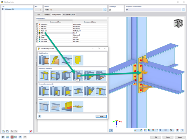
Za pomocą elementu "Żebro" można zdefiniować dowolną liczbę żeber podłużnych na blasze pręta. Wskazując obiekt odniesienia, można automatycznie określić na nim spoiny.
Komponent typu „żebro” może być również umieszczony na okrągłych profilach zamkniętych. Dafür wird zusätzlich die Vorgabe der Winkel zwischen den Rippen benötigt.

- 002720
- Ogólne informacje
- Analiza stateczności konstrukcji RFEM 6
- Analiza stateczności konstrukcji RSTAB 9
Stosując modalny współczynnik istotności (MRF) można ocenić, w jakim stopniu poszczególne elementy konstrukcyjne przyczyniają się do powstania rzeczywistego kształtu wyboczenia. Obliczenia opierają się na energii względnego odkształcenia sprężystego każdego pojedynczego pręta.
Dzięki MRF można rozróżnić lokalne i globalne kształty wyboczenia. Jeżeli kilka prętów ma znaczny MRF (np. > 20%), bardzo prawdopodobna jest niestateczność całej konstrukcji lub jej części. Jeżeli jednak suma wszystkich MRF dla kształtu drgań wynosi około 100%, należy spodziewać się lokalnego problemu ze statecznością (np. wyboczenia pojedynczego pręta).
Ponadto MRF może być wykorzystany do określenia obciążeń krytycznych i równoważnych długości wyboczeniowych poszczególnych prętów (np. do analizy stateczności). Kształty wyboczenia, dla których dany pręt ma małe wartości MRF (np. <20%), mogą zostać w tym kontekście pominięte.
MRF jest wyświetlany według kształtów wyboczenia w tabeli wyników w sekcji Analiza stateczności --> Wyniki według prętów --> Długości efektywne i obciążenia krytyczne.

W Centrum Dlubal dostępna jest obszerna biblioteka połączeń dla rozszerzenia Połączenia stalowe.
Dostęp do tej biblioteki można uzyskać bezpośrednio z rozszerzenia i przydzielić wstępnie zdefiniowane połączenia do odpowiednich węzłów. Połączenia zdefiniowane przez użytkownika można również zapisywać w bibliotece w Centrum Dlubal.
- 002073
- Ogólne informacje
- Analiza stateczności konstrukcji RFEM 6
- Analiza stateczności konstrukcji RSTAB 9
- Obliczanie modeli składających się z elementów prętowych, powłokowych i bryłowych
- Nieliniowa analiza stateczności
- Możliwość uwzględniania sił osiowych od wstępnego sprężenia
- Cztery dostępne solvery do rozwiązywania równań dla efektywnego obliczania różnych modeli konstrukcyjnych
- Opcjonalne uwzględnianie zmian w sztywności w programie RFEM/RSTAB
- Wyszukiwanie postaci wyboczeniowych o krytycznym mnożniku obciążenia większym niż zadany przez użytkownika (metoda "przesunięcia")
- Możliwość określania wektorów własnych dla modeli niestatecznych (w celu zidentyfikowania przyczyny niestateczności)
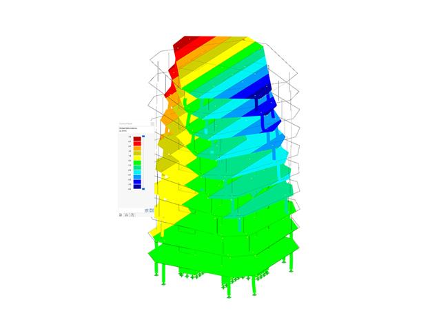
- Wizualizacja postaci niestateczności
- Podstawa określania imperfekcji

Wyniki naprężeń i odkształceń według powierzchni można wyświetlić w tabeli wyników powierzchni zgodnie z grubością warstwy.
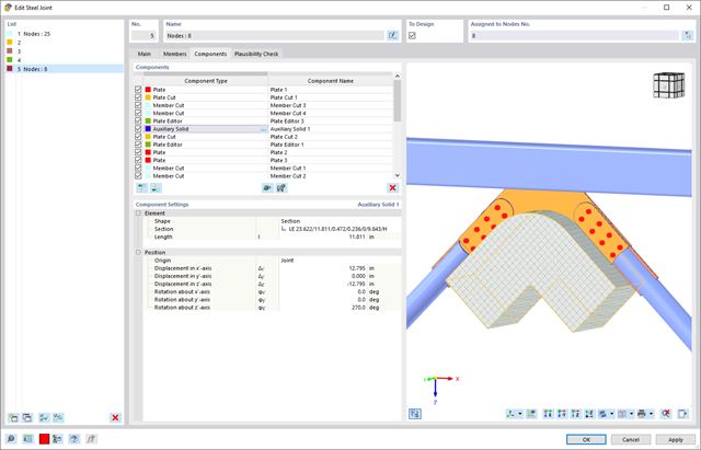
W rozszerzeniu Połączenie stalowe można użyć elementu "Bryła pomocnicza", aby dokładnie ciąć płyty i inne elementy konstrukcyjne. W ramach tego elementu, rolę obiektu pomocniczego mogą pełnić kształty takie jak sześcian, walec lub dowolny przekrój.
Przejdź do filmu
- Wybór węzłów w modelu RFEM, automatyczne rozpoznawanie i przydzielanie prętów połączonych z wybranym węzłem
- Dostępnych jest wiele wstępnie zdefiniowanych elementów ułatwiających wprowadzanie typowych komponentów połączeń (np. blachy czołowe, żebra usztywniające)
- Uniwersalne komponenty bazowe (płyty, spoiny, płaszczyzny pomocnicze) do odwzorowania złożonych geometrii połączeń
- Użytkownik nie musi ręcznie edytować modelu MES połączenia, podstawowe ustawienia obliczeń można zmienić w oknie konfiguracji połączenia
- Automatyczne dostosowywanie geometrii połączenia, nawet w przypadku późniejszej edycji prętów, z uwagi na parametryczną definicję położenia komponentów względem siebie
- Równolegle do wprowadzania danych program przeprowadza kontrolę poprawności, aby szybko wykryć brakujące dane wejściowe lub kolizje elementów.
- Wizualizacja geometrii połączenia, która jest aktualizowana równolegle z wprowadzaniem danych
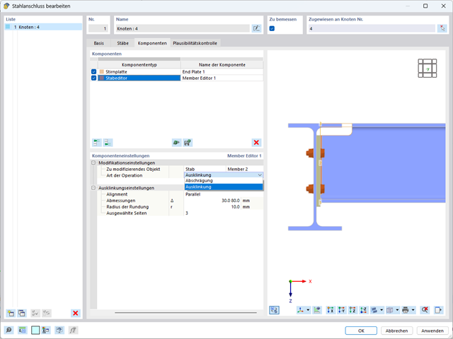
W komponencie Edytor pręta jako obiekt zmieniający można również wybrać cały pręt zamiast poszczególnych blach. W ten sposób obie operacje, "Podcięcie" i "Faza", można wykorzystać dla kilku blach danego profilu.

- 002074
- Ogólne informacje
- Analiza stateczności konstrukcji RFEM 6
- Analiza stateczności konstrukcji RSTAB 9
Jeżeli w programie istnieje przypadek obciążenia lub kombinacja obciążeń, obliczenia stateczności są aktywowane. Można zdefiniować inny przypadek obciążenia, na przykład w celu uwzględnienia naprężenia początkowego.
W tym celu należy określić, czy ma zostać przeprowadzona analiza liniowa czy nieliniowa. W zależności od przypadku zastosowania, można wybrać bezpośrednią metodę obliczeniową, taką jak metoda Lanczosa lub metoda iteracji ICG. Pręty niezintegrowane z powierzchniami są zazwyczaj wyświetlane jako elementy prętowe z dwoma węzłami ES. W przypadku zastosowania takich elementów program nie może określić wyboczenia lokalnego pojedynczych prętów. Z tego względu'istnieje możliwość automatycznego dzielenia prętów.