16 Wyniki
Wyświetl wyniki:
Sortuj według:
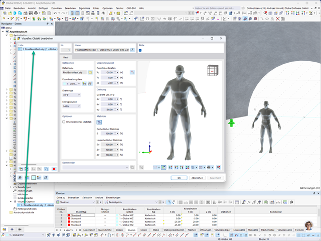
W programach RFEM 6 i RSTAB 9 można wstawić "Obiekty wizualne" jako obiekty pomocnicze. Możliwy jest import plików w formatach 3ds, stl i obj.
Obiekty te umożliwiają lepsze odniesienie do wymiarów.

W rozszerzeniu Analiza geotechniczna dostępny jest model Hoek'a-Brown'a. Model wykazuje zachowanie materiału liniowo-sprężystego idealnie plastycznego. Jego nieliniowe kryterium wytrzymałości jest najczęściej stosowanym kryterium zniszczenia skał.
Parametry materiału można wprowadzić bezpośrednio za pomocą
- parametrów skały lub alternatywnie poprzez
- klasyfikację GSI.
opisane.
Weiterführende Informationen zu diesem Materialmodell und der Definition der Eingabe in RFEM finden Sie im entsprechenden Kapitel im Online-Handbuch für das Add-On Geotechnische Analyse: Model Hoeka-Browna .
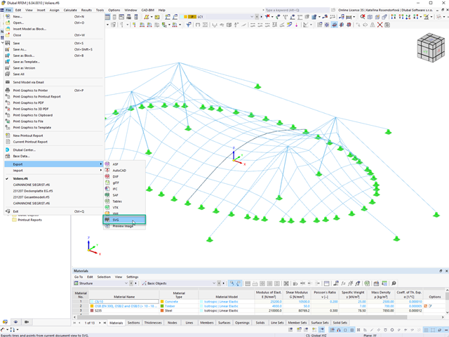
W programach RFEM 6 i RSTAB 9 można eksportować grafikę liniową do formatu SVG (grafika wektorowa).
SVG to skrót od Scalable Vector Graphics i jest formatem opartym na XML, służącym do wyświetlania dwuwymiarowej grafiki wektorowej. Takie grafiki wektorowe można skalować bez żadnych strat. Pliki SVG można edytować za pomocą edytorów tekstu, umieszczać na stronach internetowych i otwierać w popularnych przeglądarkach.
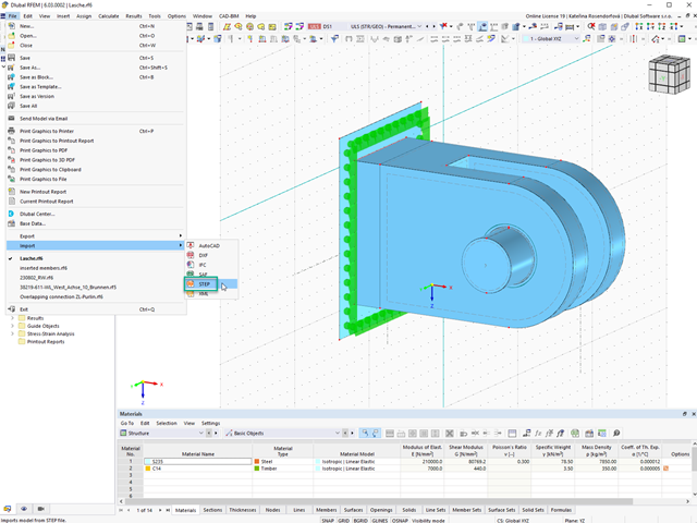
Pliki STEP można importować do programu RFEM 6. Dane są bezpośrednio konwertowane na natywne dane modelu RFEM.
STEP to standard interfejsu zainicjowany przez ISO (ISO 10303). W opisie geometrii wszystkie kształty istotne dla programu RFEM (modele liniowe, powierzchniowe i bryłowe) istotne dla programu RFEM mogą być zintegrowane za pomocą modeli danych CAD.
Uwaga: Tego formatu nie należy mylić z interfejsami DSTV, które również używają rozszerzenia *.stp.
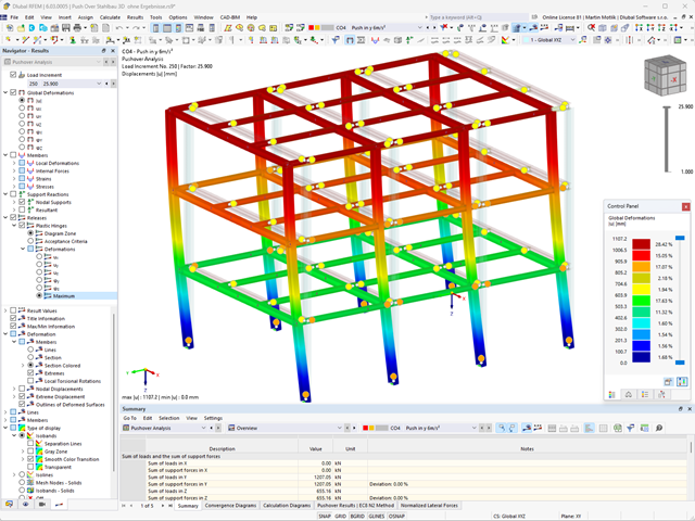
- Uwzględnienie nieliniowego zachowania komponentu przy użyciu standardowych przegubów plastycznych dla stali (FEMA 356, EN 1998-3) i nieliniowego zachowania materiału (mur, stal - bilinearnie, krzywe robocze zdefiniowane przez użytkownika)
- Bezpośredni import mas z przypadków obciążeń lub kombinacji w celu przyłożenia stałych obciążeń pionowych
- Zdefiniowane przez użytkownika specyfikacje dotyczące uwzględniania obciążeń poziomych (ujednoliconych ze względu na postać drgań lub równomiernie rozłożonych na wysokości mas)
- Wyznaczanie krzywej pushover z możliwością wyboru kryterium granicznego obliczeń (zawalenie lub odkształcenie graniczne)
- Transformacja krzywej pushover w spektrum nośności (format ADRS, układ o jednym stopniu swobody)
- Bilinearyzacja spektrum nośności zgodnie z EN 1998-1:2010 + A1:2013
- Transformacja zastosowanego spektrum odpowiedzi w wymagane spektrum (format ADRS)
- Wyznaczanie docelowego przemieszczenia zgodnie z EC 8 (metoda N2 zgodnie z Fajfar 2000)
- Graficzne porównanie nośności i wymaganego spektrum
- Graficzna ocena kryteriów akceptacji zdefiniowanych przegubów plastycznych
- Wyświetlanie wyników obliczeń iteracyjnych docelowego przemieszczenia
- Dostęp do wszystkich wyników analizy statyczno-wytrzymałościowej w poszczególnych poziomach obciążenia

- 002457
- Ogólne informacje
- Projektowanie konstrukcji aluminiowych RFEM 6
- Projektowanie konstrukcji aluminiowych RSTAB 9
Rozszerzenie Projektowanie konstrukcji aluminiowych oferuje dodatkowe opcje. W tym miejscu można również obliczać przekroje ogólne, które nie są wstępnie zdefiniowane w bibliotece przekrojów. Na przykład, utwórz przekrój w programie RSECTION, a następnie zaimportuj go do RFEM/RSTAB. W zależności od zastosowanej normy projektowej dostępne są różne formaty obliczeń. Obejmuje to na przykład równoważną analizę naprężeń.
Ist zudem eine Lizenz für RSECTION und „Effektive Querschnitte“ vorhanden, so können Sie die Nachweise auch unter Berücksichtigung der effektiven Querschnittswerte nach EN 1999-1-1 führen.
- 002331
- Ogólne informacje
- Projektowanie konstrukcji stalowych RFEM 6
- Projektowanie konstrukcji stalowych RSTAB 9
Rozszerzenie Projektowanie konstrukcji stalowych pomaga między innymi w wymiarowaniu ogólnych przekrojów, które nie są wstępnie zdefiniowane w bibliotece przekrojów. W tym celu należy utworzyć przekrój w programie RSECTION, a następnie zaimportować go do RFEM/RSTAB. W zależności od zastosowanej normy projektowej dostępne są różne formaty obliczeń. Jedną z nich jest na przykład analiza równoważnych naprężeń. Masz licencję na RSECTION i Przekroje efektywne? Następnie można przeprowadzić obliczenia z uwzględnieniem efektywnych właściwości przekrojów zgodnie z EN 1993-1-5.
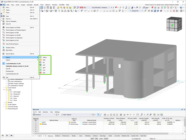
Ulepszenie, które korzystnie wpłynie na Twój przepływ pracy: Teraz można eksportować modele RFEM i RSTAB do XML, SAF i VTK (wyniki z RWIND).
.jpg?mw=640&hash=26a7c7d3eca4bc6f129e08b373eac4f2314109ba)
Pójdź o krok dalej w projektowaniu konstrukcji. Programy RFEM 6 i RSTAB 9 obsługują teraz nowy format plików do wymiarowania konstrukcji, Structural Analysis Format (SAF). W tym celu obydwa programy umożliwiają zarówno import, jak i eksport. SAF to format pliku oparty na programie MS Excel, który ma ułatwić wymianę modeli do analizy statyczno -wytrzymałościowej pomiędzy różnymi aplikacjami.

- 002129
- Ogólne informacje
- Projektowanie konstrukcji stalowych RFEM 6
- Projektowanie konstrukcji stalowych RSTAB 9
- Szeroki wybór dostępnych przekrojów, takich jak dwuteowniki walcowane; ceowniki; teowniki; kątowniki; profile zamknięte prostokątne i okrągłe; pręty okrągłe; przekroje symetryczne i niesymetryczne, parametryczne przekroje dwuteowe, teowe, kątowniki; przekroje złożone (przydatność do obliczeń zależy od wybranej normy)
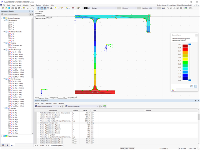
- Wymiarowanie ogólnych przekrojów RSECTION (w zależności od formatów obliczeniowych dostępnych w odpowiedniej normie); na przykład obliczanie naprężeń zastępczych
- Wymiarowanie prętów o zbieżnym przekroju (metoda zależna od normy)
- Możliwe jest dostosowanie istotnych współczynników obliczeniowych i parametrów normowych
- Elastyczność dzięki szczegółowym opcjom ustawień dla podstawy i zakresu obliczeń
- Szybkie i przejrzyste wyświetlanie wyników dla globalnej oceny ich rozkładu na konstrukcji po zakończeniu obliczeń
- Szczegółowe wyniki obliczeń i niezbędne wzory (jasna i łatwa do zweryfikowania ścieżka wyników)
- Przejrzyste zestawienie wyników w formie numerycznej w stosownych oknach oraz możliwość ich graficznego przedstawienia na konstrukcji
- Integracja wyników z protokołem wydruku programu RFEM/RSTAB

- 002140
- Ogólne informacje
- Projektowanie konstrukcji aluminiowych RFEM 6
- Projektowanie konstrukcji aluminiowych RSTAB 9
- Szeroki wybór dostępnych przekrojów, takich jak dwuteowniki walcowane; ceowniki; teowniki; kątowniki; profile zamknięte prostokątne i okrągłe; pręty okrągłe; przekroje symetryczne i niesymetryczne, parametryczne przekroje dwuteowe, teowe, kątowniki; przekroje złożone (przydatność do obliczeń zależy od wybranej normy)
- Wymiarowanie ogólnych przekrojów RSECTION (w zależności od formatów obliczeniowych dostępnych w odpowiedniej normie); na przykład obliczanie naprężeń zastępczych
- Wymiarowanie prętów o zbieżnym przekroju (metoda zależna od normy)
- Możliwe jest dostosowanie istotnych współczynników obliczeniowych i parametrów normowych
- Elastyczność dzięki szczegółowym opcjom ustawień dla podstawy i zakresu obliczeń
- Szybkie i przejrzyste wyświetlanie wyników dla globalnej oceny ich rozkładu na konstrukcji po zakończeniu obliczeń
- Szczegółowe wyniki obliczeń i niezbędne wzory (jasna i łatwa do zweryfikowania ścieżka wyników)
- Przejrzyste zestawienie wyników w formie numerycznej w stosownych oknach oraz możliwość ich graficznego przedstawienia na konstrukcji
- Integracja wyników z protokołem wydruku programu RFEM/RSTAB
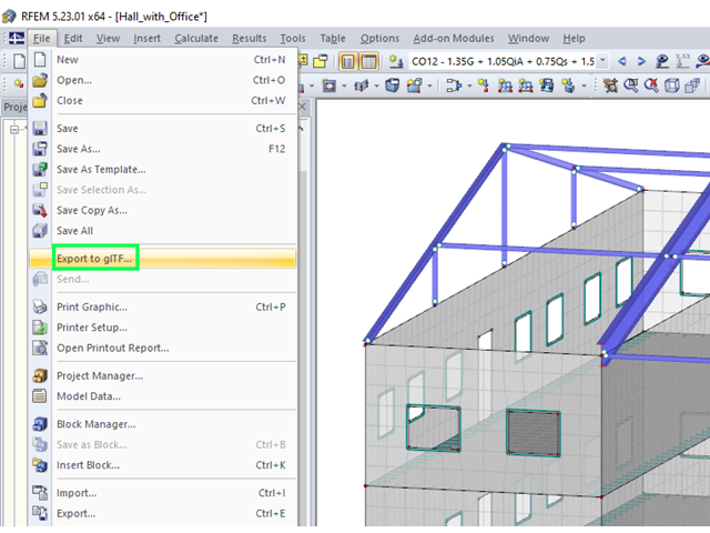
Modele z programów RFEM i RSTAB mogą być zapisywane jako modele 3D glTF (formaty *.glb i *.glTF). Obejrzyj szczegółowo modele w 3D w przeglądarce 3D firmy Google lub Babylon. Na "spacer" po konstrukcji zabierz okulary VR, takie jak Oculus.
Modele 3D glTF można zintegrować z własną stroną internetową za pomocą JavaScript, zgodnie z poniższą instrukcją (tak jak na stronie Dlubal Models do pobrania): "Łatwe wyświetlanie interaktywnych modeli 3D w Internecie i w AR" .
- Generator konstrukcji dla typowych geometrii z obciążeniami i kombinacjami
- Import i eksport danych z arkuszy kalkulacyjnych, takich jak MS Excel i MS Access
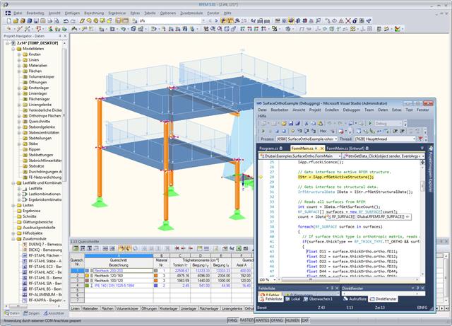
- Połączenie z różnymi programami kompatybilnymi z COM, na przykład B. Systemy CAD
- Indywidualne moduły pre- i postprocesingu
- Przetwarzanie i wyniki danych w formatach zdefiniowanych przez użytkownika
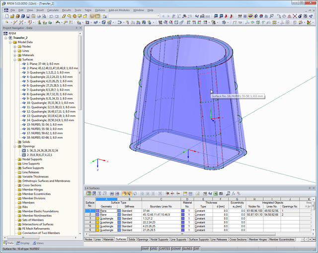
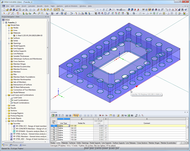
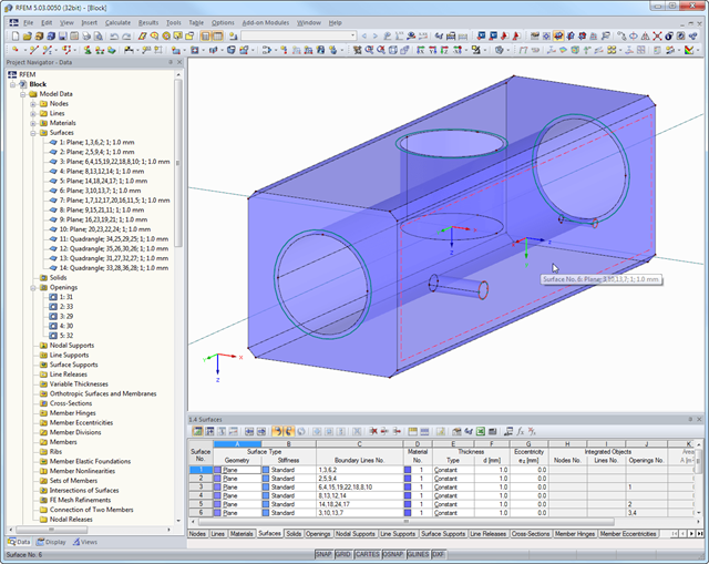
Format STEP stanowi standardowy interfejs zainicjowany przez ISO (ISO 10303). W specyfikacji topologii wszystkie kształty (modele linii, powierzchni i brył) istotne dla programu RFEM mogą być przeniesione z modeli CAD.
Uwaga: format ten bardzo różni się od interfejsu produktu DSTV (Deutscher Stahlbau Verband), który wykorzystuje to samo rozszerzenie *.stp.
Initial Graphics Exchange Specification (IGES) jest neutralnym, wysoce niezależnym formatem danych, używanym do wymiany informacji cyfrowych pomiędzy programami CAD (projektowanie wspomagane komputerowo).
Format pliku ACIS SAT jest mniejszy niż inne formaty 3D, co oszczędza czas podczas importowania i eksportowania modeli. Eksport obsługuje obecnie format ACIS 7.0.
Ponadto SAT jest uważany za szczególnie niezawodny, a wszystkie dane dotyczące geometrii i topologii, w stosownych przypadkach w programie RFEM, są przechowywane w bardzo dokładnych modelach SAT.