Japonský architektonický institut (AIJ) v souladu se srovnávacími testy pro Windsimulation vorgestellt.
Podle nového návrhu "Případ A - výšková budova ve tvaru 2:1:1".
Im Folgenden wird das beschriebene Szenario in RWIND2 nachgebildet and die Ergebnisse se simulierten and der experimentellen Resultate des AIJ verglichen.
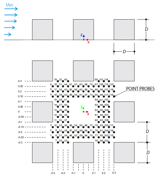
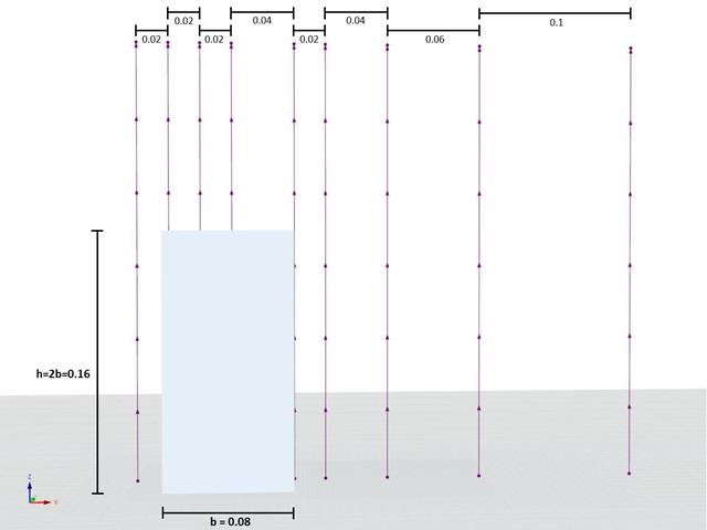
Verifikační příklad popisuje zatížení větrem v několika směrech proudění větru na modelu skupiny budov. The model consists of eight cubes. The velocity fields obtained by the RWIND simulation are compared with the measured values from the experiment. The experimental data are measured using a thermistor anemometer in the wind tunnel.
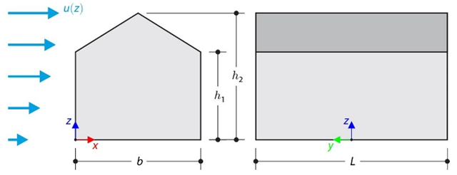
This verification example compares wind load calculations on a duopitch roof building using the ASCE 7-16 standard and using CFD simulation in RWIND Simulation. Budova je zadána v souladu s náčrtem. Rychlostní profil proudění vzduchu byl definován podle normy ASCE 7-16.
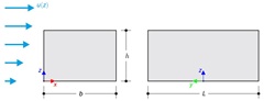
This verification example compares wind load calculations on a flat roof building using the ASCE 7-16 standard and using CFD simulation in RWIND Simulation. Budova je zadána v souladu s náčrtem. Rychlostní profil proudění vzduchu byl definován podle normy ASCE 7-16.
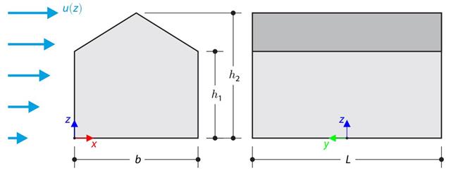
Verifikační příklad porovnává výpočet zatížení větrem na budovu se sedlovou střechou podle normy EN 1991-1-4 a pomocí CFD simulace v programu RWIND Simulation. The building is defined according to the sketch, and the inflow velocity profile is taken according to the standard EN 1991-1-4.
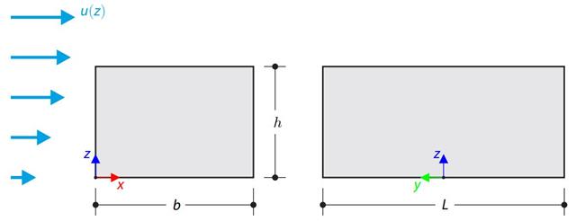
Verifikační příklad porovnává výpočet zatížení větrem na budovu s plochou střechou podle normy EN 1991-1-4 a pomocí CFD simulace v programu RWIND Simulation. The building is defined according to the sketch, and the inflow velocity profile is taken according to the standard EN 1991-1-4.
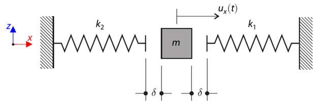
Hmotový systém s vůlí a dvěma pružinami se nejdříve vychýlí. Determine the natural oscillations of the system - deflection, velocity, and acceleration time course.
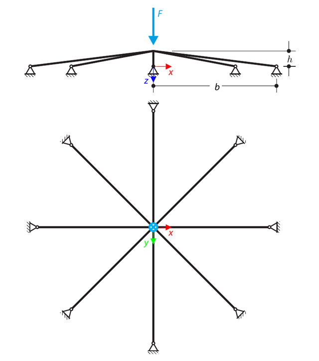
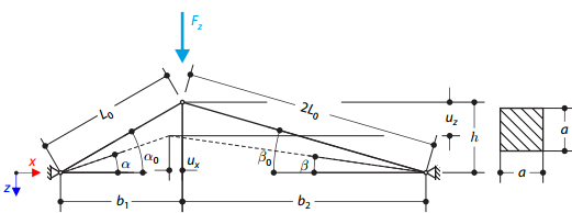
A symmetrical shallow structure is made of eight equal truss members, which are embedded into hinge supports. The structure is loaded by a concentrated force and alternatively by imposed nodal deformation over the critical limit point when the snap-through occurs. Imposed nodal deformation is used in RFEM 5 and RSTAB 8 to obtain the full equilibrium path of the snap-through. Vlastní tíha se v tomto příkladu nezohledňuje. Determine the relationship between the actual loading force and the deflection, considering large deformation analysis. Evaluate the load factor at the given deflections.
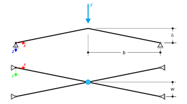
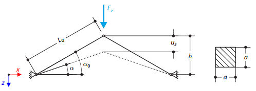
Konstrukce se skládá ze čtyř prutů, které jsou uloženy na kloubových podporách. The structure is loaded by a concentrated force and alternatively by imposed nodal deformation over the critical limit point, when snap-through occurs. Imposed nodal deformation is used in RFEM 5 and RSTAB 8 to obtain the full equilibrium path of the snap-through. The self-weight is neglected in this example. Determine the relationship between the actual loading force and the deflection, considering large deformation analysis. Evaluate the load factor at given deflections.

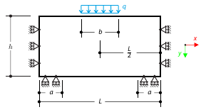
Konzola z obdélníkového průřezu leží na pružném Pasternakově podloží a je zatížena rovnoměrným zatížením. The image shows the calculation of the maximum deflection and maximum bending moment.
Konstrukce se skládá ze dvou nosníků různé délky, které jsou uloženy na kloubových podporách. The structure is loaded by concentrated force. The self-weight is neglected. Determine the relationship between the loading force and the deflection, considering large deformations.
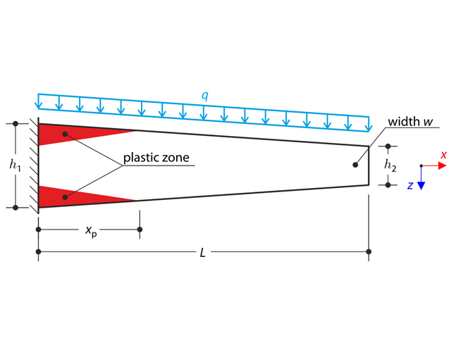
Konzola s náběhy je plně fixována na levém konci a zatížena spojitým zatížením. Plastic material is considered for the calculation.
Konstrukce se skládá ze dvou nosníků, které jsou uloženy na kloubových podporách. The structure is loaded by concentrated force. The self-weight is neglected. Determine the relationship between the loading force and the deflection, considering large deformations.
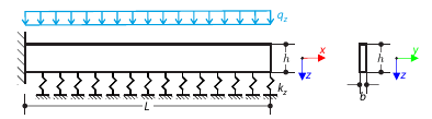
Konzola obdélníkového průřezu leží na pružném Winklerově podloží a je zatížena rovnoměrným zatížením. The image shows the calculation of the maximum deflection and maximum bending moment.
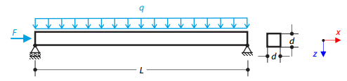
Ocelový nosník se čtvercovým průřezem je zatížen normálovou silou a spojitým zatížením. The image shows the calculation of the maximum bending deflection and critical load factor according to the second-order analysis.
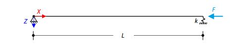
Osově zatížený ocelový nosník se čtvercovým průřezem je na jednom konci kloubově uložený a na druhém pružně podepřený. Two cases with different spring stiffnesses are considered. The verification example solves the calculation of the load factors of the beam in the image using the linear stability analysis.