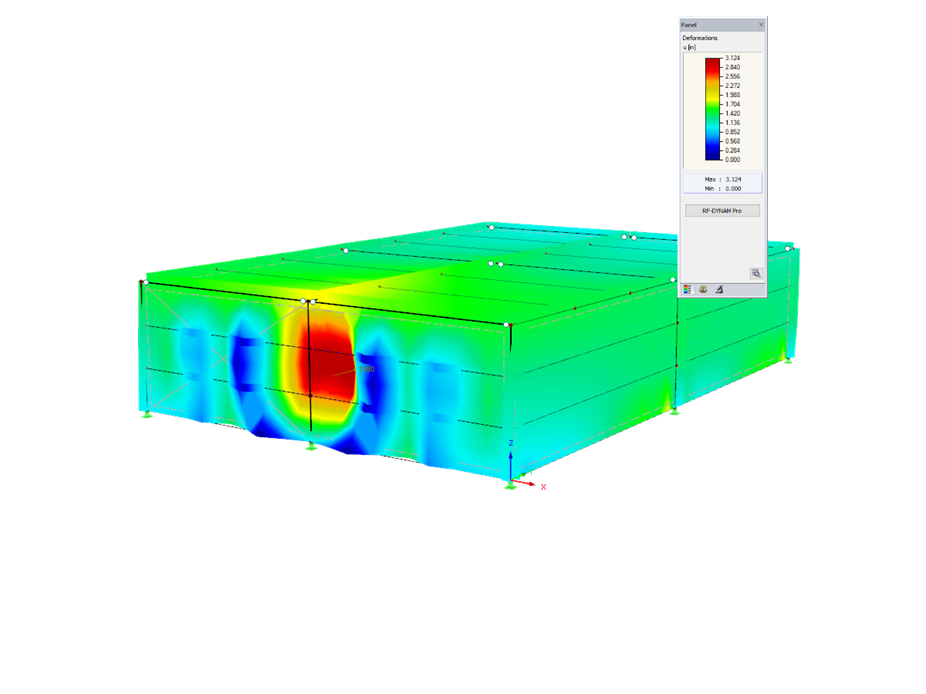
3D steel structure including a blast time history dynamic analysis.
Blast Time History Analysis of Steel Structure
Number of Nodes | 63 |
Number of Lines | 129 |
Number of Members | 77 |
Number of Surfaces | 5 |
Number of Load Cases | 4 |
Total Weight | 47.416 tons |
Dimensions | 50.4 x 70.4 x 15.2 feet |
Program Version | 5.27.00 |
You can download this structural model to use it for training purposes or for your projects. However, we do not assume any guarantee or liability for the accuracy or completeness of the model.
The Steel Design add-on for RFEM 6 / RSTAB 9 performs the ultimate limit state and the serviceability limit state design of steel members according to the Canadian standard CSA S16.
Furthermore, you can also design cold-formed steel sections according to the Canadian standard CSA S136.
Steel Design Add-on for RFEM 6In the "Edit Section" dialog box, you can display the buckling shapes of the Finite Strip Method (FSM) as a 3D graphic.
- Design of five types of seismic force-resisting systems (SFRS) includes Special Moment Frame (SMF), Intermediate Moment Frame (IMF), Ordinary Moment Frame (OMF), Ordinary Concentrically Braced Frame (OCBF), and Special Concentrically Braced Frame (SCBF)
- Ductility check of the width-to thickness ratios for webs and flanges
- Calculation of the required strength and stiffness for stability bracing of beams
- Calculation of the maximum spacing for stability bracing of beams
- Calculation of the required strength at hinge locations for stability bracing of beams
- Calculation of the column required strength with the option to neglect all bending moments, shear, and torsion for overstrength limit state
- Design check of column and brace slenderness ratios
The seismic design result is categorized into two sections: member requirements and connection requirements.
The "Seismic Requirements" include the Required Flexural Strength and the Required Shear Strength of the beam-to-column connection for moment frames. They are listed in the ‘Moment Frame Connection by Member’ tab. For braced frames, the Required Connection Tensile Strength and the Required Connection Compressive Strength of the brace are listed in the ‘Brace Connection by Member’ tab.
The program provides the performed design checks in tables. The design check details clearly display the formulas and references to the standard.