


Do you have any questions about Dlubal products or need assistance in selecting the right one for your project?
I'm here to help. You can easily reach me through the contact options provided below.
Looking forward to hearing from you!


Design of Craneway Girders
CRANEWAY | Features
- Craneway and weld stress analysis
- Craneways and weld fatigue design
- Strain
- Plate buckling analysis for wheel load introduction
- Stability analysis for lateral torsional buckling according to the second-order analysis of torsional buckling (1D FEA element)
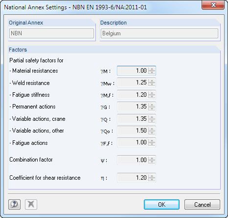
For the design according to Eurocode 3, the following National Annexes are available:
-
 DIN EN 1993-6/NA:2010-12 (Germany)
-
 NBN EN 1993-6/ANB:2011-03 (Belgium)
-
 SFS EN 1993-6/NA:2010-03 (Finland)
-
 NF EN 1993-6/NA:2011-12 (France)
-
 UNI EN 1993-6/NA:2011-02 (Italy)
-
 LST EN 1993-6/NA:2010-12 (Lithuania)
-
 NEN EN 1993-6/NB:2012-05 (Netherlands)
-
 NS EN 1993-6/NA:2010-01 (Norway)
-
 SS EN 1993-6/NA:2011-04 (Sweden)
-
 CSN EN 1993-6/NA:2010-03 (Czech Republic)
-
 BS EN 1993-6/NA:2009-11 (United Kingdom)
-
 CYS EN 1993-6/NA:2009-03 (Cyprus)
In addition to the National Annexes listed above, you can also define a specific NA, applying user-defined limit values and parameters.
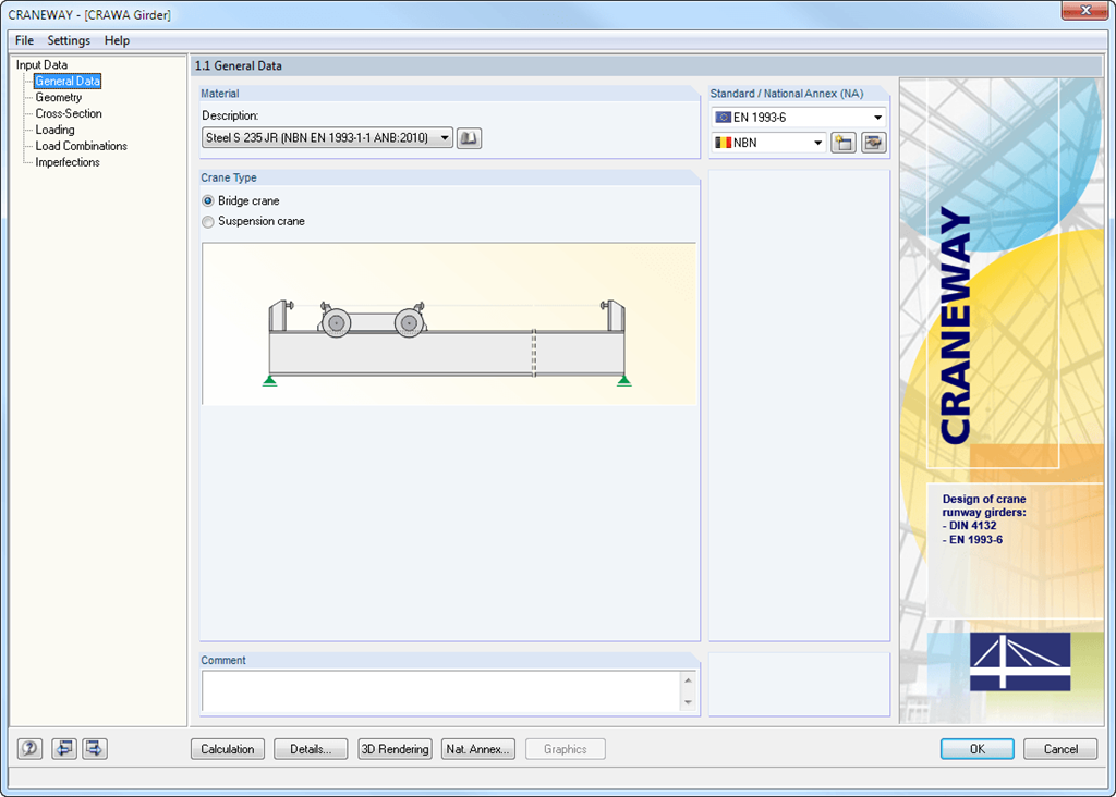
CRANEWAY | Input
Geometry, material, cross-section, action, and imperfection data are entered in clearly arranged input windows:
Geometry
- Quick and convenient data input
- Definition of support conditions based on various support types (hinged, hinged movable, rigid, and user-defined, as well as lateral on upper or bottom flange)
- Optional specification of warping restraint
- Variable arrangement of rigid and deformable support stiffeners
- Possibility to insert hinges
CRANEWAY Cross-Sections
- I-shaped rolled cross-sections (I, IPE, IPEa, IPEo, IPEv, HE-B, HE-A, HE-AA, HL, HE-M, HE, HD, HP, IPB-S, IPB-SB, W, UB, UC, and other cross-sections according to AISC, ARBED, British Steel, Gost, TU, JIS, YB, GB, and others) combinable with section stiffener on the upper flange (angles or channels) as well as rail (SA, SF) or splice with user-defined dimensions
- Unsymmetrical I-sections (type IU) also combinable with stiffeners on the upper flange as well as with rail or splice
Actions
It is possible to consider the actions of up to three simultaneously operated cranes. You can simply select a standard crane from the library. You can also enter data manually:
- Number of cranes and crane axles (maximum of 20 axles per crane), center distances, position of crane buffers
- Classification in damage classes with editable dynamic factors according to EN 1993-6, and in lifting classes and exposure categories according to DIN 4132
- Vertical and horizontal wheel loads from self-weight, hoist load, mass forces from drive, as well as loads from skewing
- Axial loading in driving direction as well as buffer forces with user-defined eccentricities
- Permanent and variable secondary loads with user-defined eccentricities
Imperfections
- The imperfection load applies in compliance with the first natural vibration mode - either identically for all load combinations to be designed, or individually for each load combination, as mode shapes may vary depending on the load.
- Convenient tools available for scaling the mode shapes (rise determination of inclination and precamber).
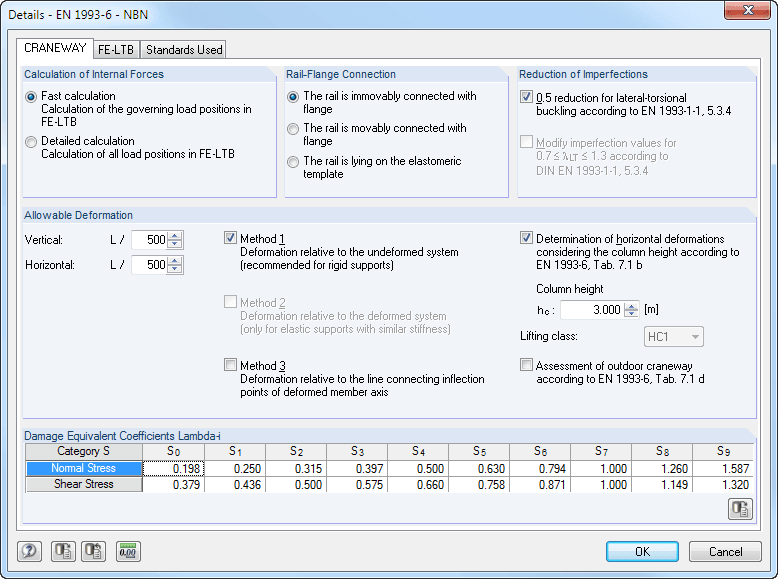
CRANEWAY | Structural Analysis
During the calculation, crane loads are generated in predefined distances as load cases of the crane runway. The load increment for cranes moving across the crane runway can be set individually.
The program analyzes all combinations of the respective limit states (ULS, fatigue, deformation, and support forces) for each crane position. In addition, there are comprehensive setting options for specification of the FE calculation, such as length of finite elements or break-off criteria.
The internal forces of a crane runway girder are calculated on an imperfect structural model according to the second-order analysis for torsional buckling.
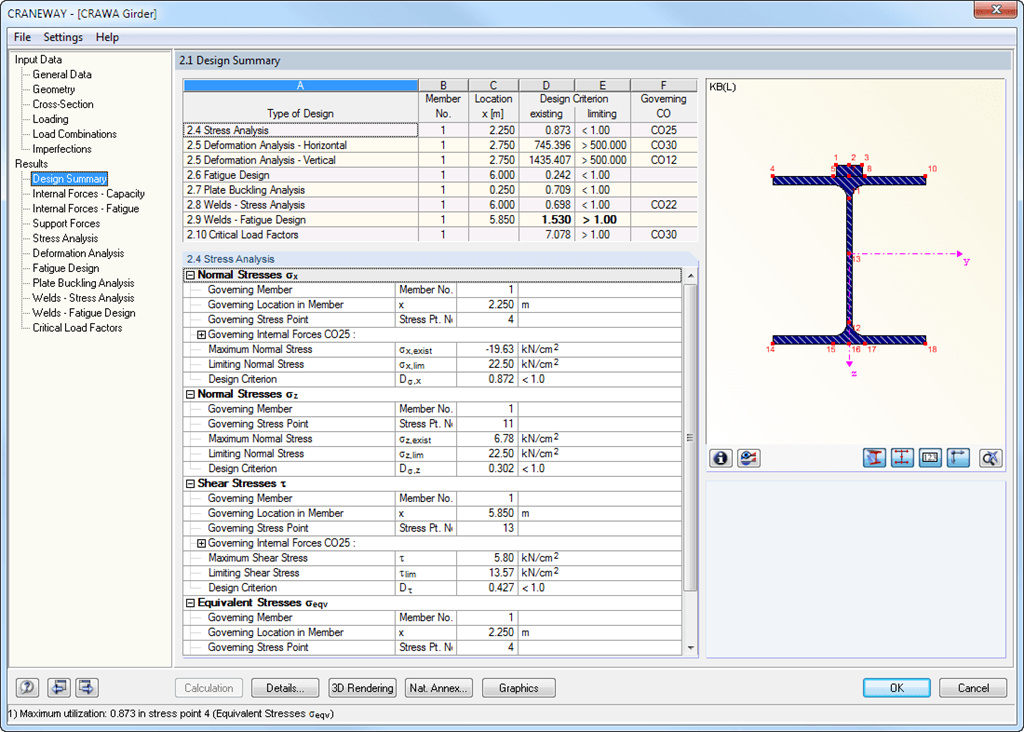
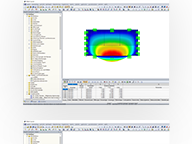
CRANEWAY | Results
All results are arranged in result windows sorted by different topics. The design values are illustrated in the corresponding cross-section graphic. The design details cover all intermediate values.
General Stress Analysis
CRANEWAY performs the general stress analysis of a craneway girder by calculating the existing stresses and comparing them with the limit normal, limit shear, and limit equivalent stresses. Welds are also subjected to the general stress analysis with regard to parallel and vertical shear stresses and their superposition.
Fatigue Design
Fatigue design is performed for up to three cranes operating at the same time, based on the nominal stress concept according to EN 1993-1-9. In the case of fatigue design according to DIN 4132, a stress curve of crane passages is recorded for each stress point and evaluated according to the Rainflow method.
Buckling Analysis
Buckling analysis considers the local introduction of wheel loads according to the EN 1993-6 or DIN 18800-3 standards.
Strain
Deformation analysis is performed separately for the vertical and horizontal directions. The available related displacements are compared to the allowable values. You can specify the allowable deformation ratios individually in the calculation parameters.
Lateral-torsional buckling analysis
The lateral-torsional buckling analysis is performed in accordance with the second-order analysis for torsional buckling considering imperfections. The general stress analysis has to be fulfilled with the critical load factor greater than 1.00. As a result, CRANEWAY displays the corresponding critical load factor for all load combinations of the stress analysis.
Support forces
The program determines all support forces on the basis of the characteristic loads, including dynamic factors.

.png?mw=192&hash=f63e4a3f1836233005de32f60201d5392e507cf1)
Calculate Your Price

The price is valid for United States.