We provide hints and tips to help you get started with the basic program RFEM.
Home Support & Learning Learning Videos FAQ 003580 | During the plausibility check, I get an error message saying that one or more polyline segments overlap each other. How can I solve this?
FAQ 003580 | During the plausibility check, I get an error message saying that one or more polyline segments overlap each other. How can I solve this?
Video
First Steps with RFEM
Question
During the plausibility check, I get an error message saying that one or more polyline segments overlap each other. How can I solve this?Answer
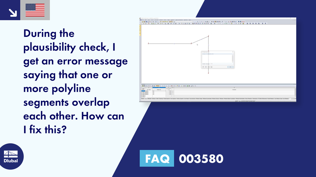
The polyline displayed in Figure 01 has been created in the order of Nodes 1 → 2 → 3 → 4 → 5. This is also visible in Column B "Node No." of Table "1.2 Lines." Thus, the line segments between Nodes 3, 4 and Nodes 4, 5 are overlapping, so that the error message shown in Figure 02 appears.
The order of the nodes must be changed in the way that no line segments overlap each other. In this example, it would be the order of Nodes 1 → 2 → 3 → 5 → 4, as shown in Figure 03.
You can also use the "Explode Polyline" function to decompose the polyline (Figure 04). Thus, two lines are created between Node 5 and Node 4. Then, you can delete the line. For this, it is also possible to use the "Regenerate Model" function in the "Tools" menu.
Both procedures are shown in the video.
Keywords
Dlubal FAQ Polyline segment Overlapping Error No. 227 Polyline Frequently Asked Question FAQ about Dlubal Question and Answer about Dlubal
Links
Contact us
Do you have any questions about our products or need advice on selecting the products needed for your projects?
Contact us via our free e-mail, chat, or forum support or find various suggested solutions and useful tips on our FAQ page.
Recommended Events
Eurocode 5 | Timber structures according to EN 1995-1-1
Online Training 03/17/2021 8:30 AM - 12:30 PM CET
Eurocode 3 | Steel structures according to DIN EN 1993-1-1
Online Training 03/18/2021 8:30 AM - 12:30 PM CET
Eurocode 3 | Steel structures according to DIN EN 1993-1-1
Online Training 05/06/2021 8:30 AM - 12:30 PM
Eurocode 2 | Concrete structures according to DIN EN 1992-1-1
Online Training 05/11/2021 8:30 AM - 12:30 PM
Eurocode 5 | Timber structures according to DIN EN 1995-1-1
Online Training 05/20/2021 8:30 AM - 12:30 PM
RFEM | Structural dynamics and earthquake design according to EC 8
Online Training 06/02/2021 8:30 AM - 12:30 PM
Videos
Models to Download
Knowledge Base Articles

New
General method for stability designs according to EN 1993-1-1 and buckling in the main bearing plane
In EN 1993-1-1, the General Method was introduced as a design format for stability designs, which can be used for planar systems with any boundary conditions and variable structural height.
Screenshots
Product Features Articles

New
Increased Calculation Performance by Reducing the Nodal Degrees of Freedom
The number of degrees of freedom in a node is no longer a global calculation parameter in RFEM (6 degrees of freedom for each mesh node in 3D models, 7 degrees of freedom for the warping torsion analysis). Thus, each node is generally considered with a different number of degrees of freedom, which leads to a variable number of equations in the calculation.
This modification speeds up the calculation, especially for models where a significant reduction of the system could be achieved (e.g. trusses and membrane structures).
Frequently Asked Questions (FAQ)
- The scale of my graphic is not displayed in the printout report. How can I change that?
- How can I use the COM interface to B. delete all nodes or members in a model?
- Why does the vertical position of a result member in my model have no influence on the bending moment My of the member?
- Is it possible to keep the results from RWIND Simulation when deleting the FE mesh if I only adjust materials or support conditions?
- How do I model a tent roof with two cone tips?
- How can I create a curved or arched section?
- How can I change the colors of the selection and preselection?
- How are the signs for the release results of a line release and line hinges interpreted?
- After the calculation in the RF‑/DYNAM Pro - Equivalent Loads add-on module, the size of my file has increased significantly. The performance has worsened enormously. What could be the reason for this?
- Is it possible to make the generated member loads from area loads via plane to act eccentrically on the member cross-section?
Customer Projects