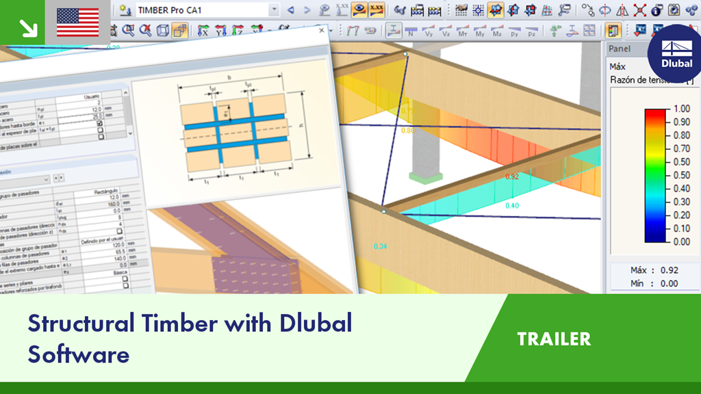
Analyze sophisticated structural timber projects with Dlubal Software. Design with national standards implemented in the various add-on modules for members and surfaces or panels as well as all joints and connections.
Trailer: Structural Timber with Dlubal Software
Links
Do you have any questions?
This article describes the design of timber panel walls due to generated horizontal loads.
The article titled Lateral-Torsional Buckling in Timber Construction | Theory explains the theoretical background for the analytical determination of the critical bending moment Mcrit or the critical bending stress σcrit for the lateral buckling of a bending beam. This article uses examples to verify the analytical solution with the result from the eigenvalue analysis.
This article shows the effect of the different stiffnesses of the timber panel walls on the floor plan.
Slender bending beams that have a large h/w ratio and are loaded parallel to the minor axis tend to have stability issues. This is due to the deflection of the compression chord.
In the RF-LAMINATE add-on module for RFEM, the design of torsional shear stresses in the superposition of net and gross cross-section values is possible. The design is performed separately in the x- and y-directions. The loads on the intersection points of cross-laminated timber panels are checked.
- General stress analysis
- Graphical and numerical results of stresses and stress ratios fully integrated in RFEM
- Flexible design with different layer compositions
- High efficiency due to few entries required
- Flexibility due to detailed setting options for basis and extent of calculations
- A local overall stiffness matrix of the surface in RFEM is generated on the basis of the selected material model and the layers contained. The following material models are available:
- Orthotropic
- Isotropic
- User-defined
- Hybrid (for combinations of material models)
- Option to save frequently used layer structures in a database
- Determination of basic, shear, and equivalent stresses
- In addition to the basic stresses, the required stresses according to DIN EN 1995-1-1 and the interaction of those stresses are available as results.
- Stress analysis for structural surfaces including simple or complex shapes
- Equivalent stresses calculated according to different approaches:
- Shape modification hypothesis (von Mises)
- Shear stress hypothesis (Tresca)
- Normal stress hypothesis (Rankine)
- Principal strain hypothesis (Bach)
- Calculation of transversal shear stresses according to Mindlin or Kirchhoff, or user-defined specifications
- Serviceability limit state design by checking surface displacements
- User-defined specifications of limit deflections
- Possibility to consider layer coupling
- Detailed results of individual stress components and ratios in tables and graphics
- Results of stresses for each layer in the model
- Parts list of designed surfaces
- Possible coupling of layers entirely without shear
- Design of hinged connections
- Biaxial inclination of the connected member (for example, a jack rafter joint)
- Connection of any number of members on one node for the type "Main member only"
- Screw diameter 6 mm – 12 mm
- Automatic check of the minimum distance between screws
- Optional free definition of screw distances
- Transfer of eccentricity from RFEM/RSTAB
- Crosswise or parallel screw alignment
- Definition of up to 16 screws in a row
- Graphical visualization of joints in the add-on module and in RFEM/RSTAB
- Performing all required designs
- Design of the following roof types:
- Flat Roof
- Monopitch roof
- Duopitch roof (symmetrical/asymmetrical)
- Definition of any additional support and free selection of degrees of freedom (additional free definition of translational and rotational spring stiffness of supports and hinges)
- Arrangement of up to five collar/tie beams, including intermediate support for duopitch roof
- Automatic generation of wind and snow loads
- Automatic generation of required combinations for the ultimate and serviceability limit states, as well as fire resistance design (additional definition of several member and nodal loads)
- For design according to EC 5 (EN 1995), the following National Annexes are available:
- Germany DIN EN 1995-1-1/NA:2013-08 (Germany)
- NBN EN 1995-1-1/ANB:2012-07 (Belgium)
- BDS EN 1995-1-1/NA:2012-02 (Bulgaria)
- DK EN 1995-1-1/NA:2011-12 (Denmark)
- SFS EN 1995-1-1/NA:2007-11 (Finland)
- NF EN 1995-1-1/NA:2010-05 (France)
- I S. EN 1995-1-1/NA:2010-03 (Ireland)
- UNI EN 1995-1-1/NA:2010-09 (Italy)
- NEN EN 1995-1-1/NB:2007-11 (Netherlands)
- ÖNORM B 1995-1-1:2015-06 (Austria)
- PN EN 1995-1-1/NA:2010-09 (Poland)
- SS EN 1995-1-1 (Sweden)
- STN EN 1995-1-1/NA:2008-12 (Slovakia)
- SIST EN 1995-1-1/A101:2006-03 (Slovenia)
- CSN EN 1995-1-1:2007-09 (Czech Republic)
- BS EN 1995-1-1/NA:2009-10 (the United Kingdom)
- CYS EN 1995-1-1/NA:2011-02 (Cyprus)
- Simple geometry input with illustrative graphics
- Input of tapered cantilevers with cut-to-grain on the bottom side of rafters
- Extensive material library that can be extended by user-defined materials
- Determination of design ratios, support forces, and deformations
- Color reference scales in result tables
- Direct data export to MS Excel
- Program languages: English, German, Czech, Italian, Spanish, French, Portuguese, Polish, Chinese, Dutch, and Russian
- Verifiable printout report, including all required designs. Printout report available in many output languages; for example, English, German, French, Italian, Spanish, Russian, Czech, Polish, Portuguese, Chinese, and Dutch.
Recommended Products for You