The stiffness modifications can be controlled separately for the following elements:
- Materials
- Cross-Sections
- Members
- Surfaces
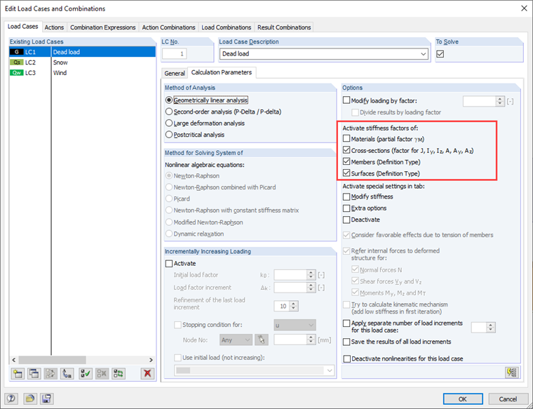
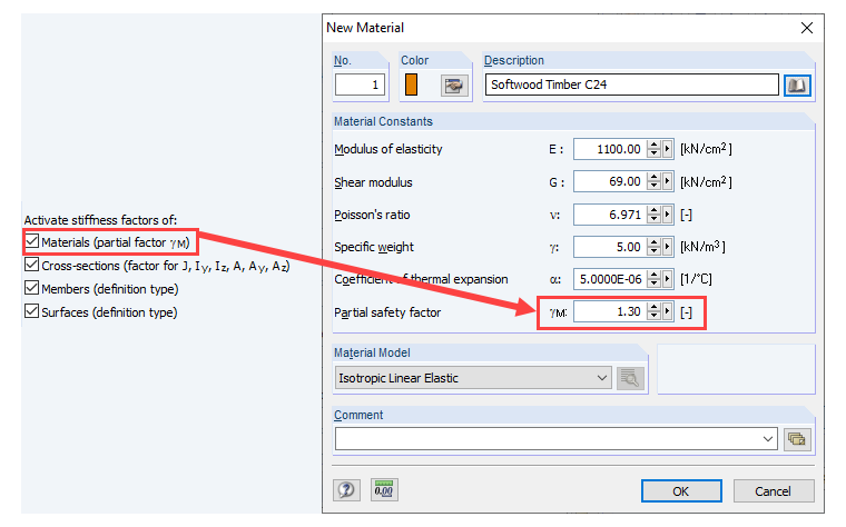
Materials
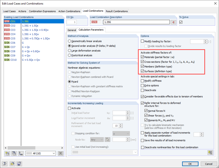
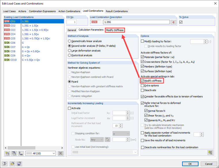
The first option "Materials" is only activated for load combinations by default (see Image 02), as the second-order analysis is preset for this. If you activate the function, the stiffness of all elements is reduced by the partial safety factor of the material (see Image 03). This is especially important for timber construction in Europe. If the automatic load combination has been selected for the standard EN 1990 + EN 1995, SIA 260 + SIA 265, or DIN 1055‑100 + DIN 18008, the default settings are different. Provided that the partial safety factor of the material is defined as 1.0, it does not matter if the function is activated or not.
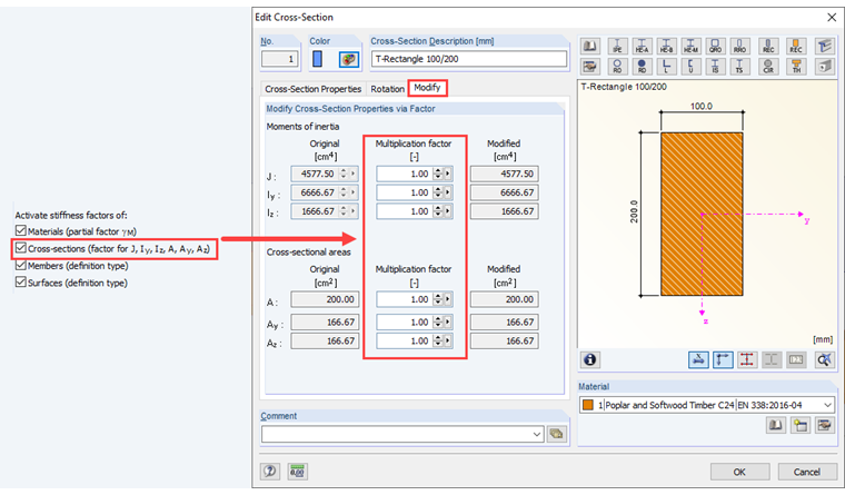
Cross-Sections
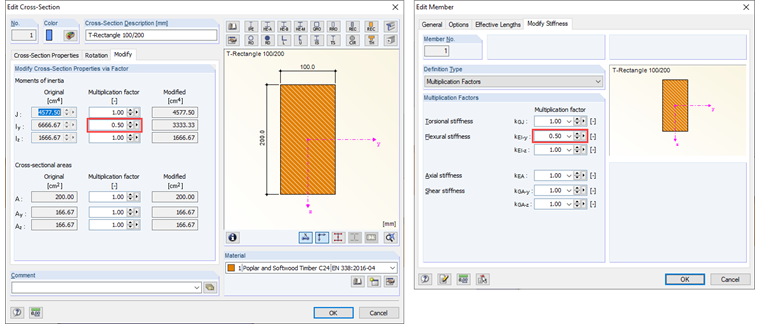
This option allows you to control the multiplication factors of the individual cross-sections. In the "Modify" tab of the "Edit Cross-Section" dialog box, you can adjust the moments of inertia as well as the cross-sectional areas. This affects the stiffness of the cross-sections.
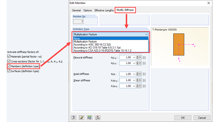
Members
When editing a member, the "Modify Stiffness" dialog tab is available. There are various definition types (see Image 05). The "Multiplication Factors" option allows you to modify the stiffness of the individual members in a similar way as the cross-sections.
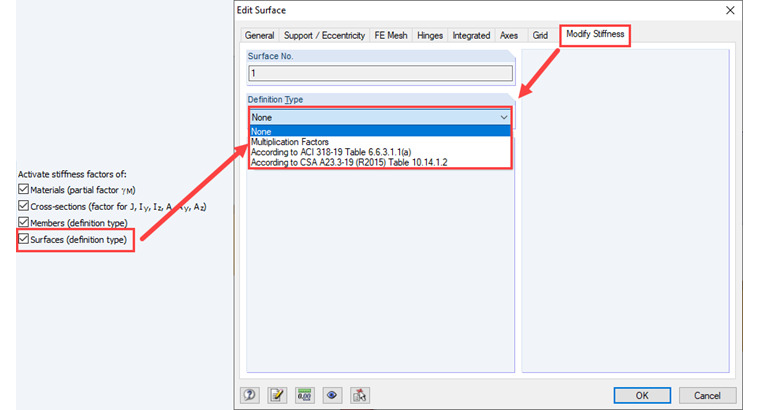
Surfaces
For surfaces of the "Standard" and "Without Tension" type, the stiffness of the surface can be adjusted in the "Modify Stiffness" tab of the "Edit Surface" dialog box. Here, you can modify the elements of a stiffness matrix by defining the factors (in the same way as in the case of orthotropic surfaces).
Further Options for Stiffness Modification
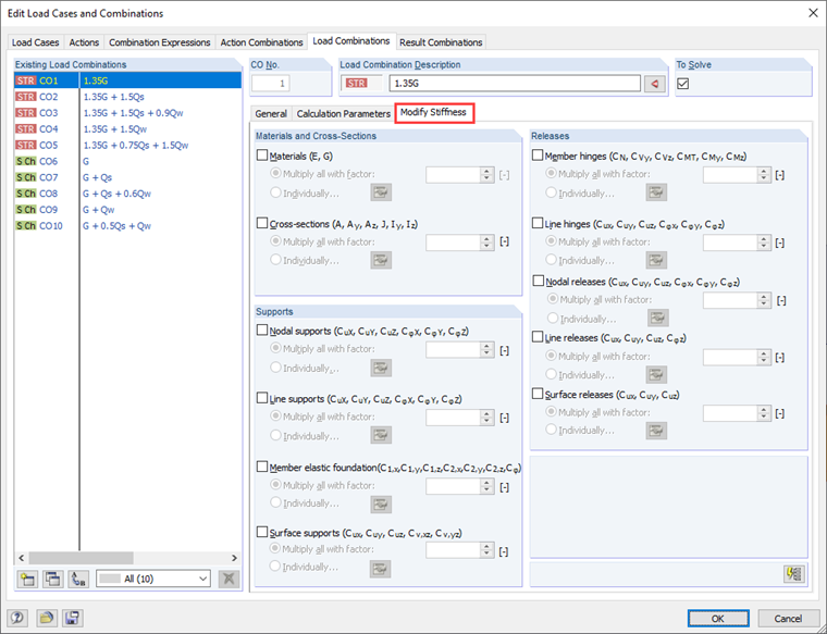
Furthermore, you can select the option in the calculation parameters to specifically adjust the stiffness of other elements (see Image 07). If you select the "Modify stiffness" option, a new tab appears (see Image 08). In addition to the member and surface stiffnesses, it is possible to individually adjust the stiffnesses of supports and releases.
Interactions of Individual Factors
If several factors have been defined for an element (for example, cross-section and member), they are multiplied by each other. For the example shown in Image 09:
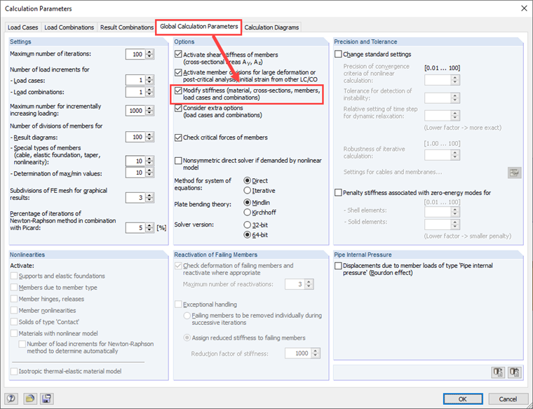
Global Control of Stiffness Modification
In the global calculation parameters (see Image 10), it is possible to deactivate all options mentioned above at once. The local settings in the calculation parameters of the load cases or the load combinations are ignored in this case.