


The RWIND Simulation program is protected against unauthorized use. The application works without restrictions on a single-user computer where the license based on a software key has been activated. To release the assigned license (for example, to use it on another single‑user computer), you can deactivate the license on the license-holding single-user computer offline via email. This FAQ also applies to RWIND 2.
To do this, proceed as follows:
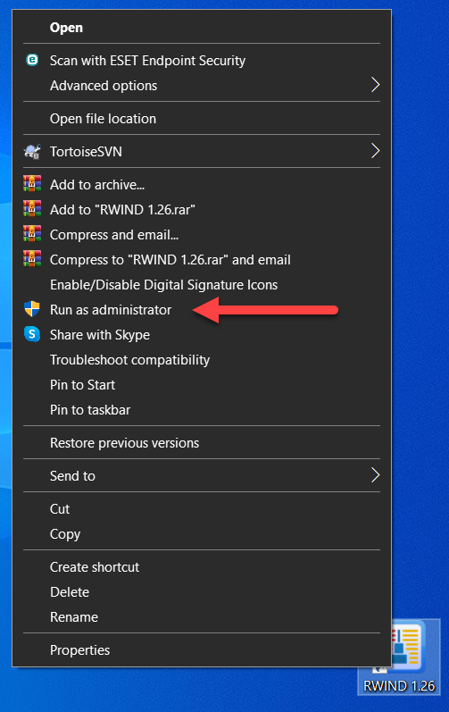
1. Run RWIND Simulation "As Administrator". To do this, right-click the RWIND Simulation icon and select "Run As Administrator".
2. Select the "RWIND Simulation - License and Authorization" function in the "Help" menu.
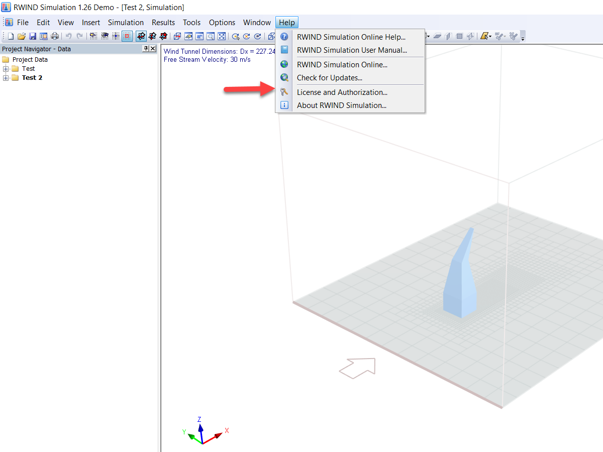
This opens the "RWIND Simulation 1.xx Authorization Status" dialog box.
3. Check in the "RWIND Simulation 1.xx Authorization Status" dialog box to see if an active software key authorization is available. This is the case if the "Software Key" option is selected in the "Authorization Method" section, and an active authorization is indicated by a green dot in the "Authorization Status" section.
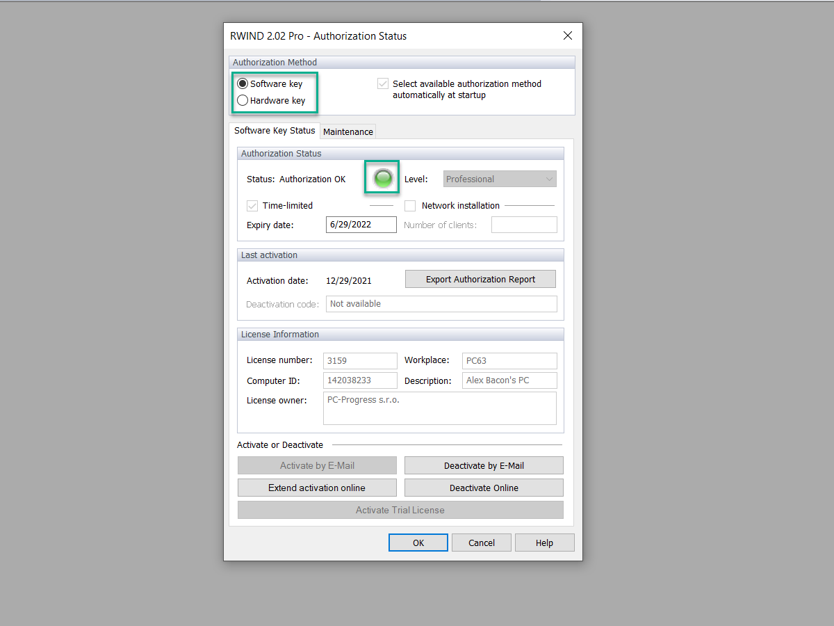
If the check is negative, and a red dot is displayed, no RWIND Simulation license based on a software key is activated on the single-user computer. As a result, no license can be deactivated.
If the requirements mentioned above are met, click the "Deactivate via Email" button. The "Deactivation of RWIND Simulation" dialog box appears.
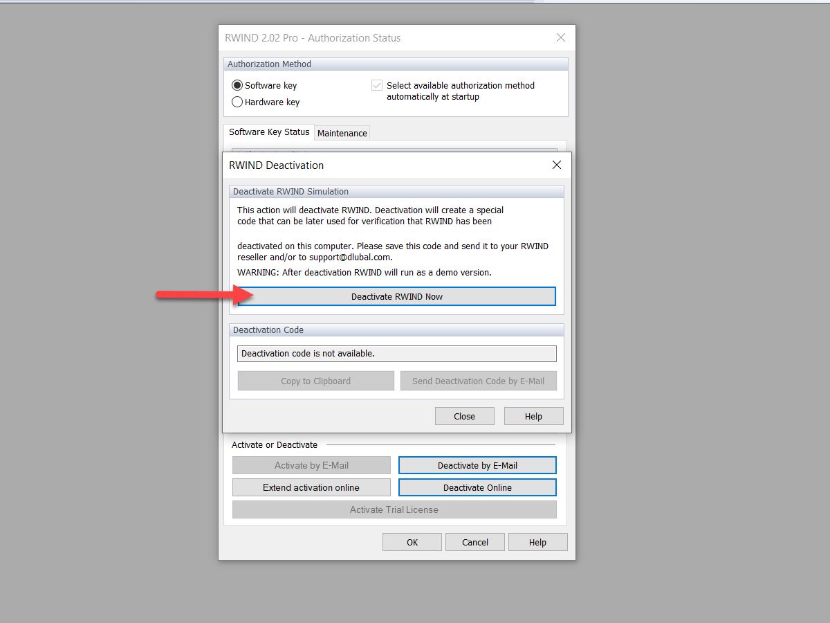
4. The "Deactivation of RWIND Simulation" dialog box explains the deactivation process.
Select the "Deactivate RWIND Simulation Now" function.
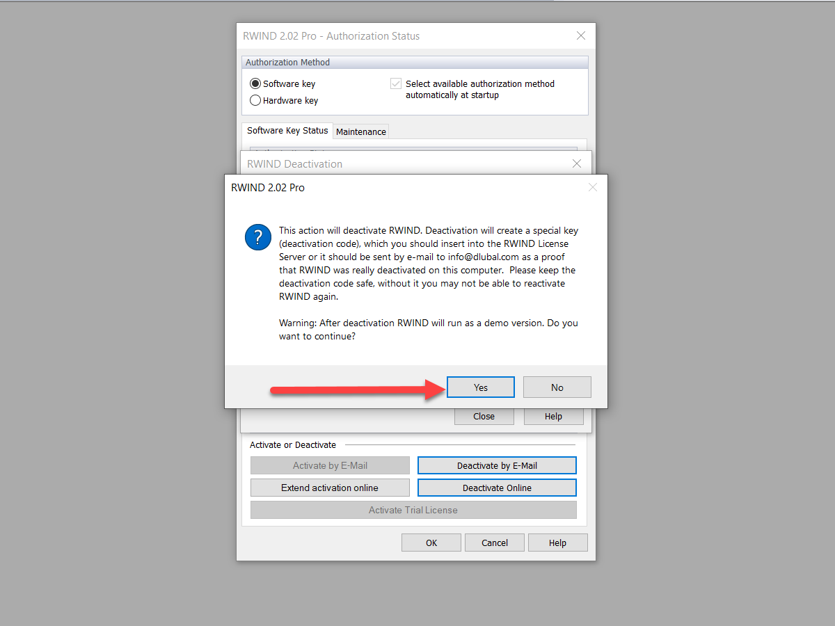
This opens the "RWIND Simulation 1.xx" dialog box.
5. In the "RWIND Simulation 1.xx" dialog box, click "Yes" to confirm the license deactivation.
After successful deactivation, you will receive a confirmation message. Now, you can only use the program in the demo mode.
The "Deactivation of RWIND Simulation" dialog box opens again.
6. The deactivation code is now displayed in the "Deactivation of RWIND Simulation" dialog box. Copy this text block to the Windows clipboard with the "Copy to Clipboard" function, then paste the code into a blank email using Ctrl+V or the Windows paste function. Send this email to [email protected] to complete the license deactivation.
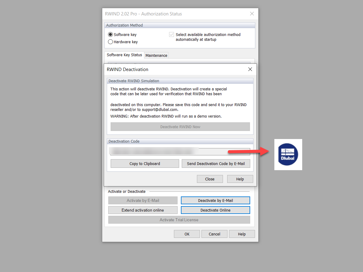
With this code, we document proper deactivation in our system.
You can now reactivate the released license on another single-user computer.