


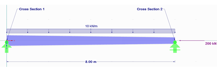
Structural System and Loading
A welded I-section of steel grade S235 has the following dimensions in mm:
Height = 500 / 300
Width = 200
Web thickness = 14
Flange thickness = 14
Weld thickness = 4
Design According to General Method 6.3.4 EN 1993-1-1
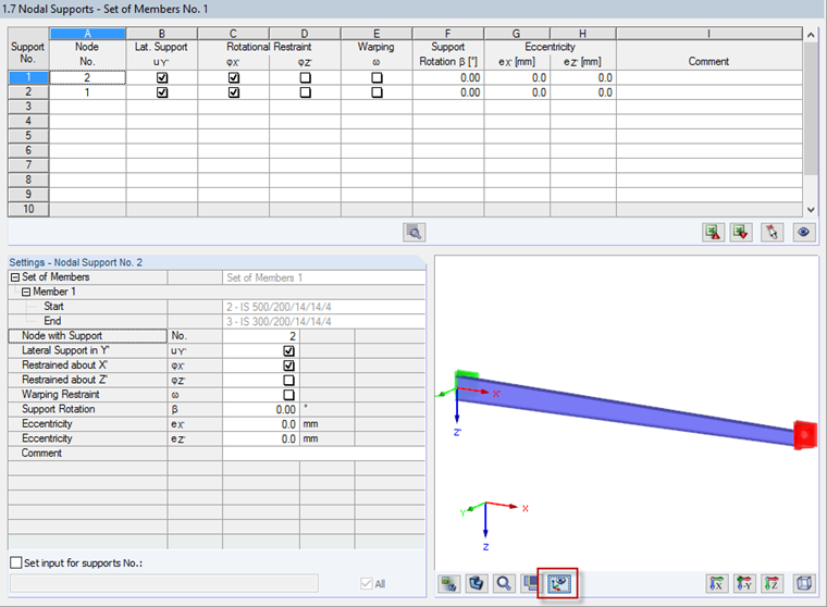
The beam design is performed as a design of a set of members in RF-/STEEL EC3. Since sets of members are designed in RF‑/STEEL EC3 according to the General Method by default, no further settings are required. In Window 1.7 Nodal Support and the corresponding partial view, you can easily check the boundary conditions of the set of members. In addition, you can check the orientation of the local coordinate system there. The local axis system can be activated by clicking the corresponding button under the partial view graphic. As is clear in the boundary conditions of the nodal supports, there are degrees of freedom in the design according to the General Method that characterize the frame plane failure. The nodal supports are to be defined as lateral and torsional restraints in this example. The preset supports already correspond to this support type, so the calculation can be started directly.
The design according to the General Method is fulfilled and gives the result of 0.97. The critical factor αcr,op is 1.647.
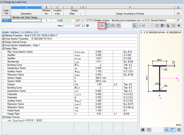
You can check the failure mode in a separate partial view window, which can be opened by clicking the [Mode Shapes] button to the right of the maximum design ratio.


Design According to Second-Order Analysis with RF-/STEEL Warping Torsion
In order to compare the results of the design according to the General Method with the design according to the second‑order analysis, the design case is duplicated by clicking "File" → "Copy Case". Now, the new design case can be adjusted for the design according to the second-order analysis. The design according to the second‑order analysis, taking into account the warping, is performed as equivalent stress design and can be selected in "Details" → "Warping Torsion".
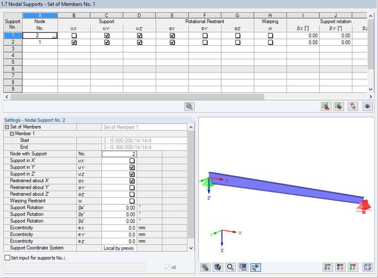
This design method is available for sets of members only. As in the first design case, the nodal supports have to be checked and adjusted. As you can see in the window for entering nodal supports, the module extension RF-/STEEL Warping Torsion does not consider only four degrees of freedom, but seven. In our example, it is important to provide member ends in the X-direction with free supports; otherwise, the axial force is not applied to the component.
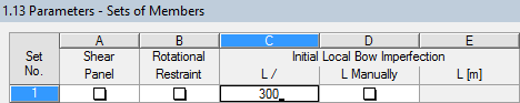
For the following design, it is important not only to enter the nodal supports but also, in particular, to specify the imperfection. You can find this in the National Annex to EN 1993‑1‑1, for example. Table NA.2 provides the corresponding information for this example: e0 / 1 = 1 / 300 applies for a welded I‑section with h/b > 2. This value has to be doubled if the slenderness ratio is in a range from 0.7 to 1.3. The slenderness ratio can be set by the value λcr,op in the first design case, according to the General Method. In our example, the value of 1/300 is set for the precamber. Finally, the design can be carried out.
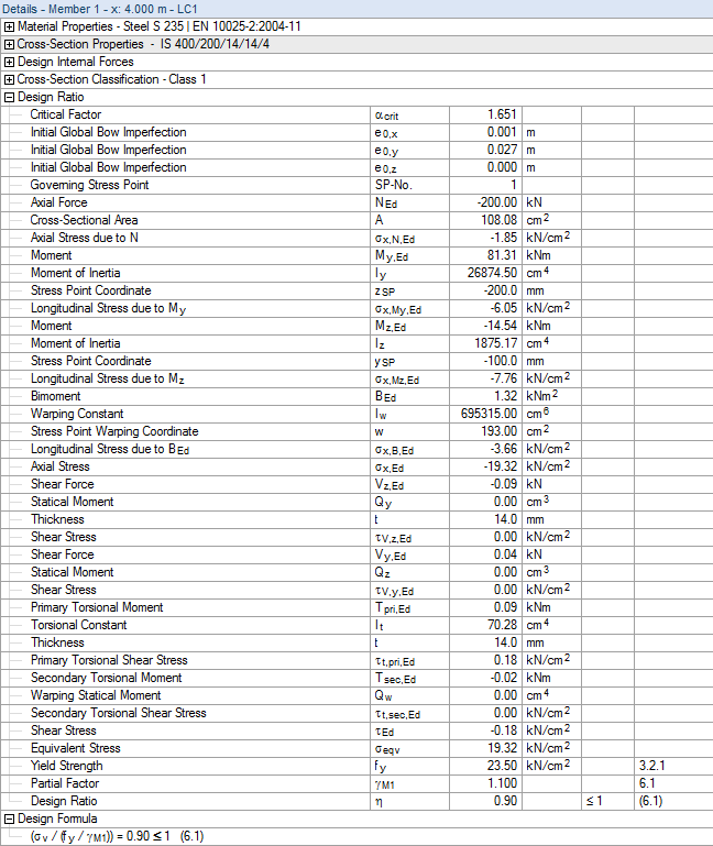
The design is fulfilled and gives the result of 0.90. The critical buckling value is 1.651.

Design According to Second‑Order Analysis with RF‑/STEEL Warping Torsion and RF-/STEEL Plasticity
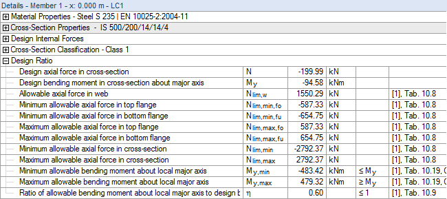
For more efficient design, the RF-/STEEL Plasticity extension of the RF-/STEEL EC3 add-on module is available. It allows you to analyze internal forces according to the second-order analysis from the warping torsion analysis with the Partial Internal Forces Method according to Kindmann for stability analysis of a set of members, or with the Simplex Method for general cross-sections.
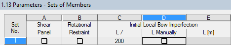
After copying the second design case, the plastic design can be activated in "Details" → "Plasticity". By copying the second design case, the correct nodal supports have already been adopted. However, it is necessary to check and adjust the imperfection. Table NA.2 indicates a value of 1/200 for the plastic design of a welded I-section with h/b > 2.
Now, the design can be performed and is fulfilled.

Conclusion
For tapered structural components, two design methods are available in RF-/STEEL EC3. In addition to the integrated General Method according to Sect. 6.3.4 of EN 1993‑1‑1, you can perform the design according to the second-order analysis, including consideration of warping in the RF-/STEEL Warping Torsion module extension. Moreover, the warping torsion analysis can apply to other cross-sections and load situations.
For more efficient design, you can perform plastic design according to the Partial Internal Forces Method (PIFM) or according to the Simplex Method in the RF-/STEEL Plasticity module extension in addition to the warping torsion analysis.