


For example, the columns should be modeled using members. Since the plate elements do not have rotational degrees of freedom, it is impossible to consider rotational springs. Therefore, it is important to model the member connection as close to reality as possible.
The example described in this article provides a comparison of different column models. The model is a plate made of concrete C25/30 with dimensions of 0.24 m ∙ 6.5 m ∙ 2.5 m. The columns have the dimensions of 0.24 m ∙ 0.45 m ∙ 2.5 m.
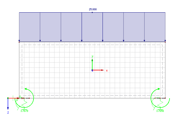
Model 1
This model applies a rigid coupling over the column width by using member elements. In the middle of this coupling, there is a nodal support with the following spring stiffnesses.
Axial force spring:
Rotational spring:
The advantage of this model is that it is not necessary to enter the columns themselves. Furthermore, you can avoid singularities very easily by using nodal supports. However, the spring values of the nodal support must be determined manually in advance.
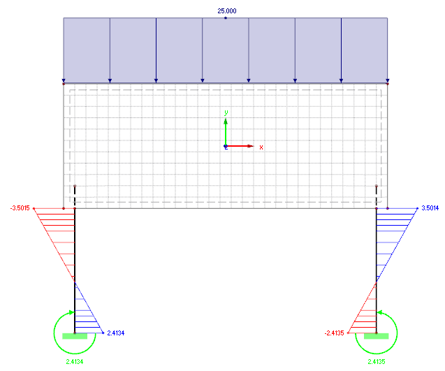
Model 2
In this model, the members of the supports continue to one or two sets of elements of the FE mesh network in the shear wall. The goal is to determine the connection between the support and the shear wall approximately close to reality. The advantage of this method is that it is not necessary to determine the springs manually, and the connection can be modeled very quickly. However, since the internal force distributions in the connection zone of the supports are often disturbed in the plate, this option can only be recommended depending on the model.
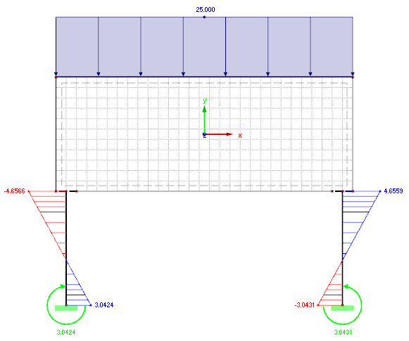
Model 3
In contrast to Model 2, the supports are not extended into the shear wall, but connected to the wall in the same way as in Model 1. The coupling stiffness should be defined sufficiently high. The advantage of this model is that the modeling is relatively fast and simple. Also in this case, it is not necessary to manually determine the spring values in advance. You can also avoid the disadvantages of the second model.
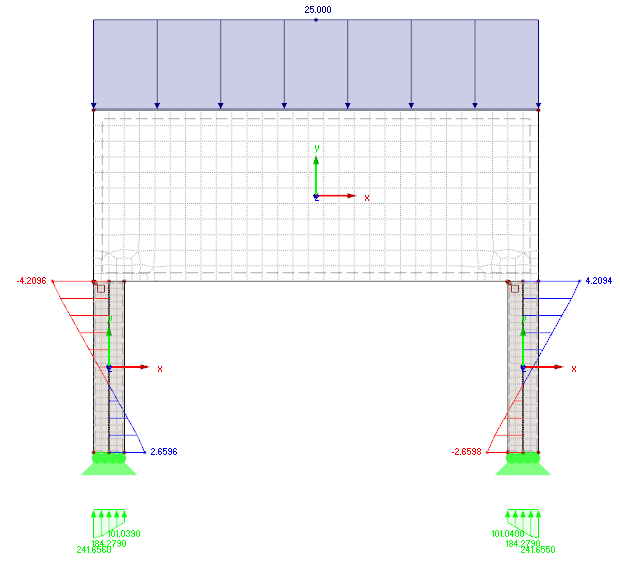
Model 4
In Model 4, the columns are modeled using surfaces with the corresponding dimensions. In order to see the comparison of the moment distribution on all of the models, the result members are defined in the middle of the columns. Thus, the surface results are integrated and the resulting internal forces are obtained. These members can also be designed in the RF-CONCRETE Members add-on module, for example.
Conclusion
Generally speaking, all models should avoid singularities by using nodal supports. All models can be created much more realistically by modeling the columns on the plate as a nodal support. The difference between the results in Model 1 can be explained by the fact that the horizontal stiffnesses of the column is completely omitted.