


A previous technical article should be mentioned here, where the punching shear design in general according to [1] and [2], as well as the features of the RF-PUNCH Pro add-on module, have been explained.
Model Example
The punching shear design will be performed for a 25-centimeter-thick reinforced concrete floor with concrete grade C30/37. The column dimensions amount to 25 x 25 cm.
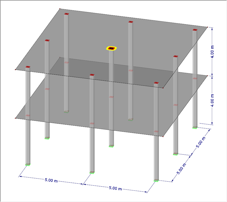
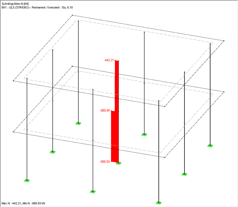
In the further course, only the punching shear design for the internal column at the connection to the floor over the ground floor will be performed. See also the colored punching shear point in Image 01. An axial force of Nd = 442.21 kN at the column head in the internal column on the first floor results from the determination of internal forces in RFEM.
Analysis with Designed Perimeters
If a punching shear design is performed in RF-PUNCH Pro, the perimeters necessary for the design (control perimeter, inner and outer perimeters) will be created automatically in the add-on module. Moreover, the default settings for the "applied punching load" or the "load increasing factor ß" can always be maintained as a general rule.
In this example, the punching load should also be used from the axial force of the column. However, the load increasing factor ß will be determined on the basis of the "constant factors" according to 6.4.3 (6). For this situation (inner column), this results in a load increasing factor ß = 1.10.
Instead of the default settings, an existing longitudinal reinforcement will be defined as well for the design of the punching shear resistance. This means that the add-on module automatically sets a shear reinforcement as soon as the defined longitudinal reinforcement on the top surface of the plate is insufficient and νRd,c < νEd.
Furthermore, the existing longitudinal reinforcement on the top surface of the plate (side without loading) will be defined with Ø 12 - 10 in both reinforcement directions, which corresponds to a reinforcement content of 11.31 cm²/m.
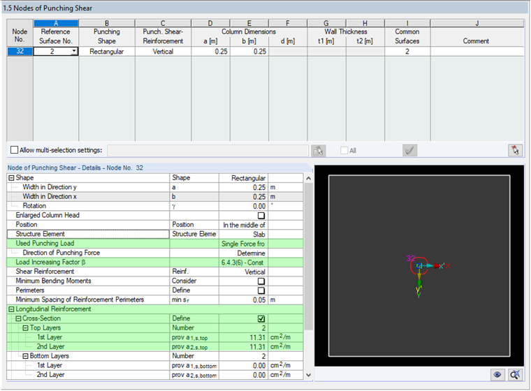
The position of the longitudinal reinforcement should be noted (Ø 12 - 10). The reinforcement to be considered for the design should, in this case, meet a concrete cover of cnom = 3.5 cm. For this purpose, the position of the reinforcement in direction 1 will be defined with d1 = cnom + ds/s = 3.5 + 1.2/2 = 4.1 cm. The concrete cover in direction 2 thus results in d2 = d1 + ds = 5.3 cm. The definition of the concrete cover in Table "1.4 Longitudinal Reinforcement" determines the dimension of the static depth d and has to be adjusted accordingly before starting the calculation.
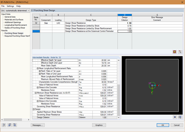
After having performed the calculation for the inputs mentioned above, the design criteria are displayed in Result Table "2.1 Punching Shear Design". A punching shear resistance νRd,c = 612.05 kN/m² is produced. The punching shear resistance without the punching shear reinforcement is thus insufficient.
Since νRd,c = 612.05 kN/m² < νEd = 674.80 kN/m², the maximum punching shear resistance νRd,max will be checked. According to 6.4.5 (3), [2] νRd,max results in:
νEd,u1 ≤ νRd,max = 1.4 · νRd,c,u1
νEd,u1 = 674.80 kN/m²
νRd,max = 1.4 · 612.05 kN/m² = 856.87 kN/m²
This design is kept with νEd = 674.80 kN/m² < νRd,max = 856.88 kN/m² with a ratio of 79% so that the module automatically starts with the design of the inner and outer perimeters.
The position of the outer perimeter results in, according to 6.4.5 (4) Equation 6.54:
uout = ß · VEd / (νRd,c · d)
Note: νRd,c for the shear resistance without shear reinforcement according to 6.2.2 (1)
With this formula, it is possible to determine the diameter of the outer perimeter and thus the distance lw,a from the outer perimeter to the edge of the load surface. Thus, it is possible to determine the "area reinforced against punching shear". According to 9.4.3 [1], the first inner perimeter can be arranged with a distance of 0.5 d from the load surface. The last inner perimeter is 1.5 d before the outer perimeter. See also Figure 2.36 in [3].
With these approaches, the module can determine the number and distances of the necessary inner perimeters automatically. This is also the case in RF-PUNCH Pro according to the default design settings, which always results in a design criterion of 1.00 in Table "2.1 Punching Shear Design" for the design of the diagonal strut as well as the outer perimeter.
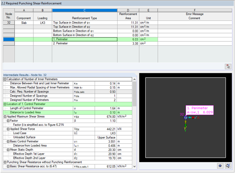
Result Table "2.2 Required Punching Shear Reinforcement" shows the longitudinal and shear reinforcement belonging to the design criteria displayed. The detail tables show, for example, the distance of the single inner perimeters (shear reinforcement series) from the edge of the load introduction.
Design with Defined Perimeters
For this example, the design of the automatic position of the inner perimeters leads to a distance of 10 cm from the edge of the load introduction for the first shear series. This value (see Image 05) is documented in the result details with lw for each of the designed perimeters. For the second inner perimeter, it results in lw,2 = lw,1 + sr = 0.10 m + 0.14 m = 0.24 m.
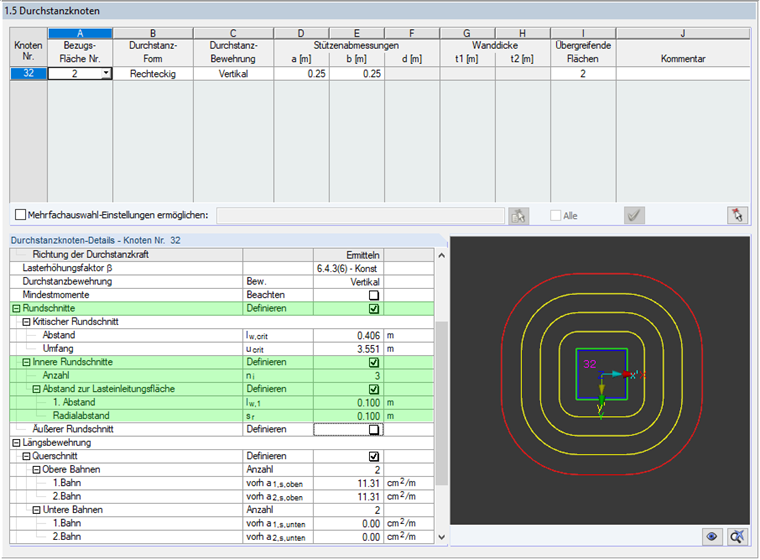
In RF-PUNCH Pro, the user also has the option to define the position of the outer and inner perimeters directly. To do this, it is necessary to activate the "Perimeters" option in Table "1.5 Nodes of Punching Shear" before starting the design. This allows, as shown in this example, defining the number and position of the "Inner Perimeters".
As an alternative to the automatically designed two inner perimeters, it is now possible to calculate with three inner perimeters, for example. It is possible to define here the number and distance of the load surface to the first inner perimeter lw,1 and the distances between the inner perimeters sr.
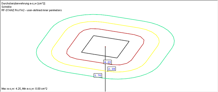
After the calculation, the necessary longitudinal and punching shear reinforcement is also displayed in Result Table "2.2. Required Punching Shear Reinforcement" with the calculated required reinforcement areas per perimeter.
If the requirements according to 9.4.3 [1] concerning the position of the single inner perimeters or the outer perimeter—for example, radial distance sr of the inner perimeters among each other ((≤ 0.75 d) or the distance from the last inner to the outer perimeter (≤ 1.5 d)—have not been met, a corresponding notice will be displayed in result table "2.2 Required Punching Shear Reinforcement". Thus, an incorrect entry can be recognized and solved quickly.
Applications and Further Information
In most cases, the punching shear design with RF-PUNCH Pro will certainly be performed in such a way that the longitudinal reinforcement is increased to a practicable degree for construction to avoid the punching shear reinforcement in the shape of shear stirrups. If the required longitudinal reinforcement—even if the maximum longitudinal reinforcement ratio φl has not yet been achieved—is no longer possible in building practice, RF-PUNCH Pro offers the option to design the required punching shear reinforcement in the form of shear stirrups (vertical or inclined) automatically. Alternatively, the engineer has the additional option to export the punching load and the punching geometry to the design program Halfen HDB, in which, as an alternative to shear stirrups, shear rails can be designed.
Irrespective of this, it may happen that an already designed punching shear reinforcement should be analyzed on a modified load situation. To enable this kind of "recalculation" or to elaborate an alternative reinforcement concept for the reinforcement planning, RF-PUNCH Pro offers the above-mentioned options of "Definition of Perimeters".
In this respect, reference is made to Section 2.2.1.5 in the RF-PUNCH Pro manual. The flowcharts for the punching shear design with punching shear reinforcement are documented there so the single steps for designing the required shear reinforcement can also be understood.