Determining Coefficients
To determine the load, the force coefficients cf and the entire pressure coefficients cp,net according to Table 7.6 to Table 7.8 should be used. If there is an obstruction below or immediately next to the roof (for example, stored goods), the degree of the obstruction has to be determined and interpolated in the tables between ϕ = 0 (unobstructed) and ϕ = 1 (totally obstructed).
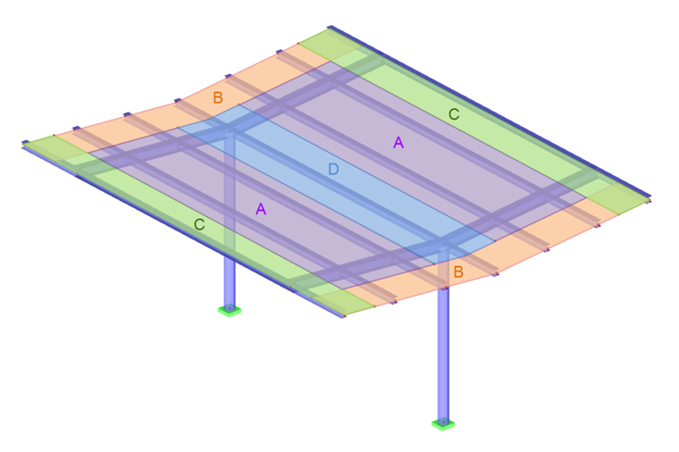
To determine the resulting entire pressure coefficient, a classification of surfaces is performed similar to that of closed buildings. This only applies to the design of the roof covering and its anchorage elements.
Position and Form of Resulting Wind Power
To design the supporting structure, it is necessary to apply the resulting wind power in the distance of d/4 of the windward side. d is the dimension for the roof surface downwind. Graphic 7.17 displays six possible load arrangements depending on the sign of the force coefficient.
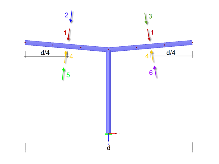
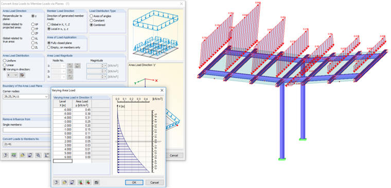
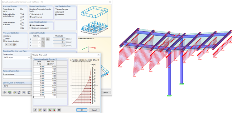
Since the wind load is acting as a surface load and not as a nodal load on the roof covering, and its centroid position amounts to 1/4 of the roof length, it is necessary to find an appropriate load situation that takes this into consideration. Such an eccentric load arrangement leads to a highly loaded stability analysis of possible central supports. One possible load arrangement would be a surface load in the shape of a square parabola, because its center of gravity is situated in 1/4 of the length.
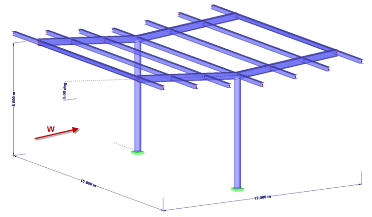
Example: Trough Roof
Length = 15 m
Width = 12 m
Height of valley = 6 m
Roof inclination = -5 °
Wind load = 0.5 kN/m²
No obstruction → ϕ = 0
cf = +0.3 maximum all ϕ
cf = -0.5 minimum ϕ = 0
Resulting Wind Force
RFEM and RSTAB contain the load generators for enclosed buildings with a rectangular ground plan. It can be selected if the load is applied only to the walls, the roof, or the entire building.
Supporting structures for canopy roofs cannot be calculated automatically. However, the load generator with levels can be used after determining the coefficients.
Friction forces according to Section 7.5 are not considered in this example.
Largest Load Ordinates of Parabolic Load
Attention is paid only to load positions 2 and 5. Load positions 3 and 6 are not necessary due to the symmetry.
With these load ordinates and using this quadratic equation, if necessary in Excel, the variable load values per x-location can be determined and exported to RFEM or RSTAB.