Modeling Member Model
RFEM provides you with the option to convert thin-walled cross-sections as members to surface models. Therefore, the member model should be created first, and afterwards, the corresponding members should be converted. The model used in this article is shown in Image 01.
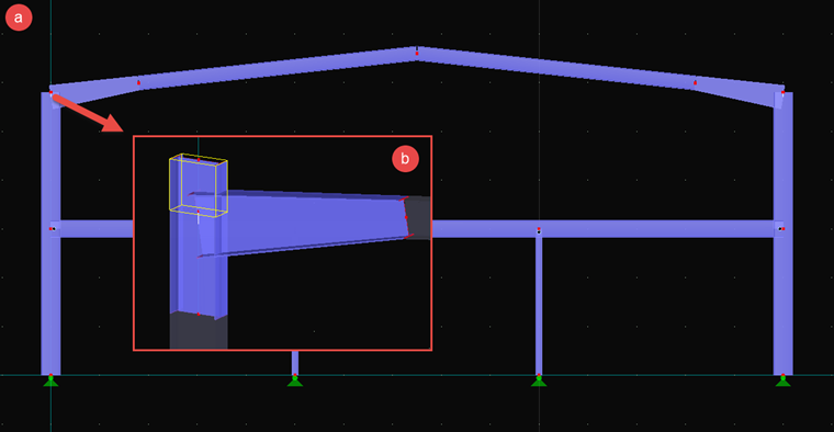
It is a single hall frame where the frame joint, highlighted with an arrow in the image, will be replaced by a surface model. The length of the members plays an important role here from two points of view.
- A surface model requires many more FE elements than a member. Therefore, we recommend choosing the smallest possible length of the member to minimize the calculation effort and thus the duration of the calculation. Otherwise, the calculation is more precise if even more FE elements and a large part of the member are defined as a surface model.
- The conversion from member to surface model requires a good load application, since the member forces have to be transferred from a node to the lines of the cross-section. To receive a load distribution that is as realistic as possible, the member should not be too short.
To meet both requirements, you can use the general rule of the load distribution at an angle of 60°. Therefore, at least the largest width of the cross-section should be applied as the length for the load application area.
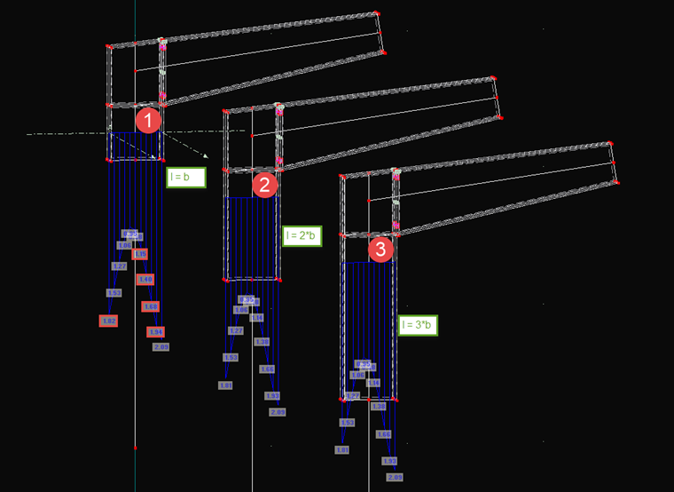
Image 02 shows a comparison of three modeled frame joints in one section that was applied at half the cross-section width w. The reference value is the von Mises equivalent stress. It is clearly evident that there are still greater differences between Option 1, with single, and Option 2, with double cross-section width with the length l. At more than triple the length in Option 3, the differences can barely be seen. Therefore, we recommend applying double the cross-section width as the length, to be on the safe side. The same applies to the girder. In the interests of simplification, no cut was performed and the entire taper was used.
Since the column should be continuous, it has to be extended upwards by one more member. The member length should be selected so that it protrudes at least over the taper, because it will be cut down to the right length later. The modified frame joint is shown in Image 01 b.
Creating Surface Model
Now, you can convert the members into surface models. To do this, right-click a member and select "Generate Surfaces". The created model has various intersections, however. Moreover, end plates, ribs, and the correct inclination of the column at the top are missing.
First of all, the intersections should be edited. To do this, select the "Connect Lines/Members" tool. If two intersecting surfaces are selected, intersection points are created at the boundary lines at the intersection. It would also be possible to create an intersection and to convert them to a line. The end points of the taper can then be moved to these new points, as shown in Image 03.
It is possible for surfaces to become incorrect or be deleted. This can be corrected later. After deleting all unnecessary lines and nodes, a model as shown in Image 04 should be present.
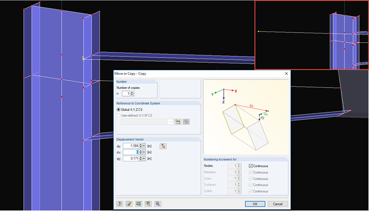
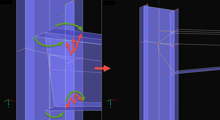
The next step is the cutting to length of the column. To display the right inclination of the taper correctly, one of the edges of the upper flange is used for the displacement vector during copying. This process is displayed in Image 04. The upper intersection point between column and girder flange is to be copied. In the "Move/Copy" dialog box, a copy is entered and selected as the vector of the start and end nodes of the girder flange edge. Since the girder is reduced, the value for this direction (here, dY) has to be set to 0. A line can now be created between both nodes. This line also intersects the opposite flange edge of the column now. You can generate the intersection point with the "Connect Lines/Members" tool.
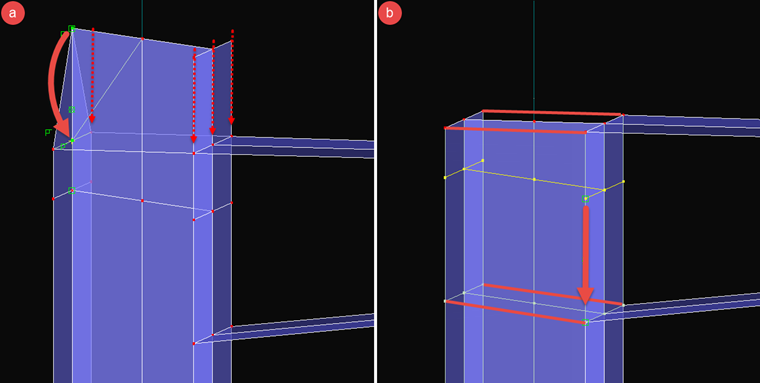
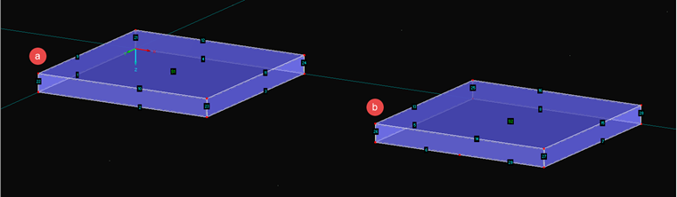
After the correct inclination is displayed, the new node is mirrored or copied to the other side of the column and the nodes of the column end are then moved to these new nodes (Image 05 a). At this point, the joint between the column and the created extension can be moved to the lower edge of the taper, and the additional lines for the stiffeners and the end plate can be created as shown in Image 05 b.
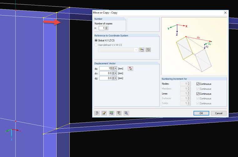
Afterwards, the end plate of the taper will be created. The intersection lines between column and girder can be copied perpendicular to the column. The distance depends on the flange and end plate thickness. Half the thickness has to be added in each case. In the current example, the flange has a thickness of 13.5 mm and the end plate, a thickness of 12 mm. This results in a distance of about 13 mm. When the lines have been copied, the lines of the girder can be moved to the new nodes at the end as well (Image 06), and the additional connection lines can be created for the end plate. After this step, the surfaces of the taper will no longer be present, since the boundary lines have been changed.
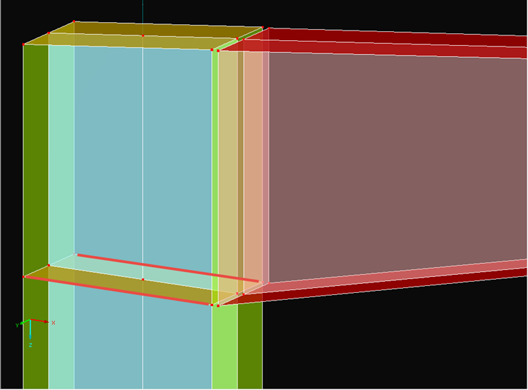
To finish the modeling, rib lines and lost and new surfaces are created. In this case, the result would look like Image 07. For a clearly arranged display, the surfaces are shown in different colors depending on the thickness.
Modeling Bolt/Flange Connection
The connection between the end plate of the girder and the flange of the column will be realized using a contact solid and members. The contact solid is placed between the two surfaces (column/girder) and can simulate failure under tension between the surfaces. The tension forces should be absorbed by the bolts that are modeled as members.
The holes are drilled first. The bases for the drilled holes are the openings in the flange and the end plate. To do this, first copy the node of the end plate at the top to the correct position (Image 08 a). At this location, a circle can be created (the work plane has to be considered). The boundary surfaces of contact solids always need to have four boundary lines. Since this is not yet the case for this hole with its inner surfaces, the circle has to be separated into two segments (insert line and use "Connect Lines/Members"). The opening can be created with "Select Boundary Lines" (Image 08 b).
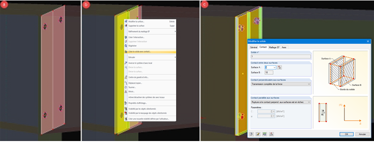
In the next step, the generated drilled hole, together with the center, is copied to the bottom. Both drilled holes can then be mirrored (Image 09 a). The contact solid, or rather, the two contact solids, are created by clicking the opposite surfaces and selecting "Create Solid with Contact" (Image 09 b). The completed contact solids are shown in the model in Image 09 c. You can set the "Failure under tension" property in the dialog box of the solids.
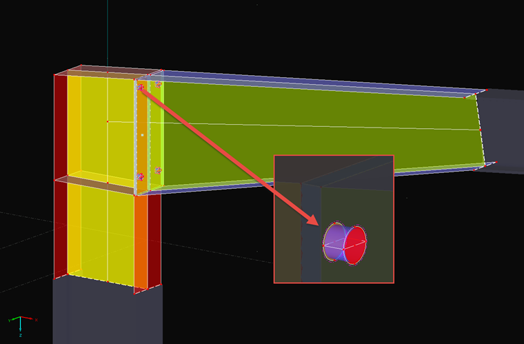
Members with a round bar cross-section can be used to model the bolts in accordance with the core diameter of the bolts used. Prestress can be applied. The connection between member and surface is carried out with a surface of the "Membrane – Without Tension" type. The failure under tension is thus simulated in the hole bearing (Image 10).
The connection to the member model is created by rigid members. Rigid members are created at both ends of the cross-section outlines of the surface model, which ensures a uniformly distributed load application of the point from the member to the surface model.
Tips & Tricks
It will be obvious whether or not the modeling is coherent when the FE mesh is generated. In the following text, three typical issues and methods for solving them will be presented.
"The definition lines of a surface are not closed."
This issue occurs if the boundary lines of a surface have been modified. In this case, several surfaces of the taper were concerned. These old surfaces have already been replaced by new surfaces, and the old incomplete surfaces can be deleted. Generally, it can be stated that correcting a surface often takes longer than generating a new one with "Selecting Boundary Lines".
"Numbers of integrated objects in contact surfaces do not correspond."
When using a contact solid, both contact surfaces have to be absolutely identical. Where a node is present in a surface, the node also has to be present along the surface normal in the other surface. The boundary surfaces have to be ordinary to both contact surfaces everywhere as well.
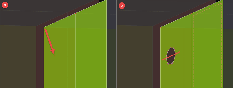
"Side surfaces XX do not have four boundary lines."
All side surfaces of a contact solid need to have four boundary lines. This also applies to holes in a contact solid. Image 11 shows a small example. In case a, the displayed boundary surface has exactly four lines (2, 22, 10, 23); in Case b, however, it has five, which is not allowed. The number of boundary lines of the contact surfaces is irrelevant, however.