Timber Beam Analysis
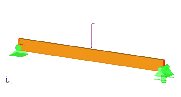
A 15-foot-long, nominal 4 inch ⋅ 14 inch Select Structural Douglas Fir-Larch (North) beam with a mid-span point load of 2.500 kip will be designed. The goal of this analysis is to determine the adjusted bending factors and bending capacity of the beam. A normal load duration and pinned supports at each end of the member are assumed. Loading criteria are simplified for this example. Normal loading criteria can be referenced in Sec. 1.4.4 [1]. In Image 01, a diagram of the simple beam with loads and dimensions is shown.
Beam Properties
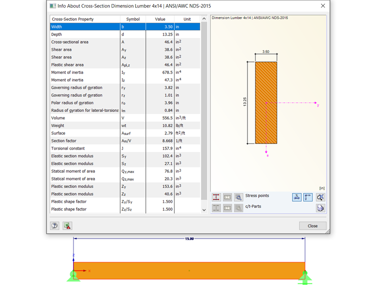
The cross-section used in this example is a 4 inch ⋅ 14 inch nominal dimension lumber. The actual cross-section property calculations of the timber beam can be viewed below:
- b = 3.50 in
- d = 13.25 in
- L = 15 ft
- Gross cross-section area:
- Section modulus:
- Moment of inertia:
The material that will be used for this example is Select Structural Douglas Fir-Larch (North). The material properties are as follows:
- Reference bending design value: Fb = 1,350 psi
- Minimum modulus of elasticity: Emin = 690,000 psi
Beam Adjustment Factors
For the design of timber members as per the 2018 NDS standard and the ASD method, stability factors (or adjustment factors) must be applied to the reference bending design value (Fb). This will ultimately provide the adjusted bending design value (F'b). The factor F'b is determined with the following equation, highly dependent on the listed adjustment factors from Table 4.3.1 [1]:
Below, each adjustment factor is determined:
CD
The load duration factor is implemented to take into account different periods of loading. Snow, wind, and earthquakes are taken into account with CD. This factor must be multiplied by all reference design values except for the modulus of elasticity (E), modulus of elasticity for beam and column stability (Emin), and the compression forces perpendicular to the grain (Fc) based on Sec. 4.3.2 [1]. CD in this case is set to 1.00 as per Sec. 2.3.2 [1], assuming a normal load duration of 10 years.
CM
The wet service factor references design values for structural sawn lumber based on moisture service conditions specified in Sec. 4.1.4 [1]. In this case, based on Sec. 4.3.3 [1], CM is set to 1.00.
Ct
The temperature factor is controlled by a member’s sustained exposure to elevated temperatures up to 150 degrees Fahrenheit. All reference design values will be multiplied by Ct. Utilizing Table 2.3.3 [1], Ct is set to 1.00 for all reference design values, assuming temperatures are lesser than or equal to 100 degrees Fahrenheit.
CF
The size factor for sawn lumber takes into account the fact that wood is not a homogeneous material. The size of the beam and type of wood are taken into account. For this example, our beam has a width between 2 inches and 4 inches and a nominal depth of 14 inches. Referencing Table 4A based on the material and size of the beam, a factor of 1.00 is applied. This info can be found in Sec. 4.3.6.1 [1].
Ci
The incising factor is used to take into account the preservative treatment wood goes through to resist decay that can cause fungal growth. Most of the time this involves pressure treatment, but in some cases it requires the wood to be incised, increasing the surface area for chemical coverage. For this example, we will be assuming the wood is incised. Referencing Table 4.3.8 [1], an overview of what factors each member properties must be multiplied by is shown.
r
The repetitive member factor is used in cases where multiple sawn lumber members act in a uniform fashion, leading to uniform load distributing amongst the members. These members cannot be spaced more than 24 inches from center. In this example, we will be assuming the beam is closely spaced and connected by either sheathing or decking. In this case, the repetitive member factor Cr is equal to 1.15 from Sec. 4.3.9 [1].
CL
The beam stability factor checks that the torsional buckling or weak-axis buckling does not happen over long non-laterally supported spans. This is in reference to Sec. 5.3.4 [1] and will be calculated below.
Cfu
The flat use factor is used when the loading of a timber member is applied to the weak axis versus the strong axis. For this example, we will be applying the loading to the strong axis, so this factor will not be included in our calculations.
CT
The buckling stiffness factor is used to take into account plywood sheathing that can increase the buckling resistance of compression truss chords. For this example, we will be assuming there is no plywood sheathing, so CT is equal to 1.00.
Adjusted Modulus of Elasticity
The reference modulus of elasticity values (E and Emin) must also be adjusted. The adjusted modulus of elasticity (E' and E'min) are determined from Table 4.3.1 [1] and the incising factor Ci is equal to 0.95 from Table 4.3.8 [1].
Beam Stability Factor (CL)
The beam stability factor (CL) is needed in order to calculate the beam's adjusted bending design value and further, to calculate the bending design ratio. The following steps will include the necessary equations and values to find CL.
The effective length of this beam can be calculated using the lateral unsupported length (lu), which is the full length of the beam. The member length converted into inches is used in the effective length equation from Table 3.3.3 [1].
Next, we will calculate the slenderness ratio of bending members (RB) utilizing Sec. 3.3.3.6 [1] with the beam width, depth, and effective span length.
Now, the critical buckling design value for bending members (Fbe) is calculated with reference to Sec. 3.3.3.8 [1]. The modulus of elasticity for beam stability (E'min) along with the previously calculated slenderness ratio of bending (RB) is used.
The beam stability factor (CL) can now be calculated with reference to the same section above.
The incising factor Ci is equal to 0.80 for Fb from Table 4.3.8 [1]. Now, all adjustment factors have been determined from Table 4.3.1 [1]. Therefore, the adjusted bending design value (F'b) can be calculated.
Beam Design Ratio
The ultimate goal of this example is to obtain the design ratio for this simple beam. This will determine if the member size is adequate under the given load, or if it should be further optimized. Calculating the design ratio requires the maximum bending moment and actual bending stress.
The maximum moment about the x-axis (Mmax) is found by the following.
Next, the actual bending stress (fb) is calculated by plugging in Mmax and S from previous calculations. This can be seen below, utilizing Sec. 3.3.2.1 [1].
Finally, the design ratio (η) as per Sec. 3.3.1 can now be calculated.
Application in RFEM
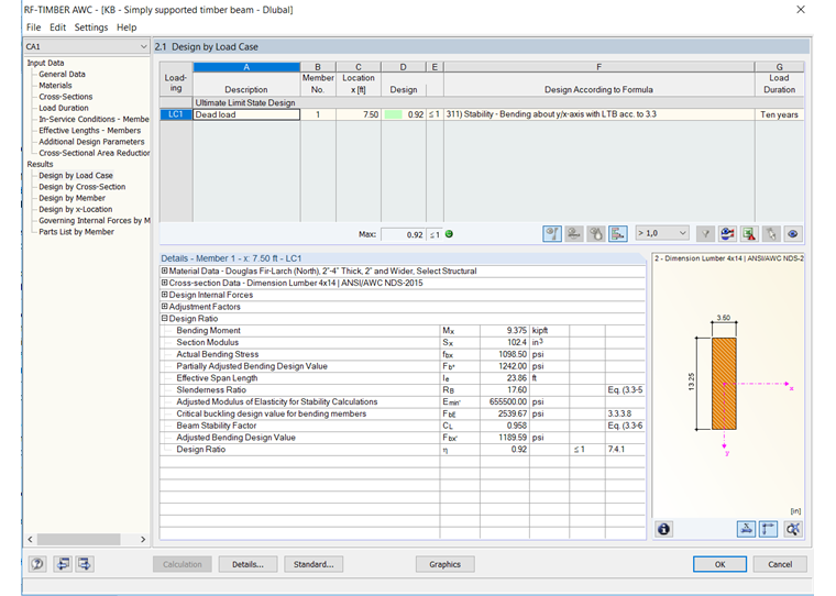
For timber design as per the 2018 NDS standard in RFEM, the add-on module RF-TIMBER AWC analyzes and optimizes cross-sections based on loading criteria and member capacity for a single member or set of members. This is available for either LRFD or ASD design methods. When modeling and designing the beam example above in RF-TIMBER AWC, the results can be compared.
In the General Data table of the RF-TIMBER AWC add-on module, the member, loading conditions, and design methods are selected. The material and cross-sections are defined from RFEM and the load duration is set to ten years. The moisture service condition is set to Dry and the temperature is equal to or less than 100 degrees Fahrenheit. Lateral-Torsional Buckling is defined as according to Table 3.3.3 [1]. The module calculations produce an actual bending stress (fb) of 1,098.50 psi and an adjusted bending design value (f'b) of 1,189.59 psi. A design ratio (η) of 0.92 is determined from these values aligning well with the analytical hand calculations shown above.