Different Calculation Options in RFEM
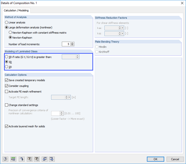
Such stress peaks can be produced or avoided by using different support arrangements. Considering certain points and knowing the program's functionality are, therefore, necessary when defining the layer structure. Basically, two calculation options are available: the "2D" and the "3D" option.
The "2D" calculation method describes internal modeling of the layer structure via surfaces. The glass panes are displayed via surface elements in RFEM. When using laminated safety glass, an equivalent thickness of the layer is determined. If the shear coupling is taken into account, however, this theory reaches its limits if the difference in stiffness is too great, meaning the "3D" option must be used.
The layer structure is modeled and calculated as solid elements. The advantage of this more time-intensive method is that the stiffnesses of each layer are precisely considered in the calculation and that relations such as shear coupling can actually be considered. In some cases, RFEM presets a calculation option that cannot be modified.
Selecting Support Arrangement
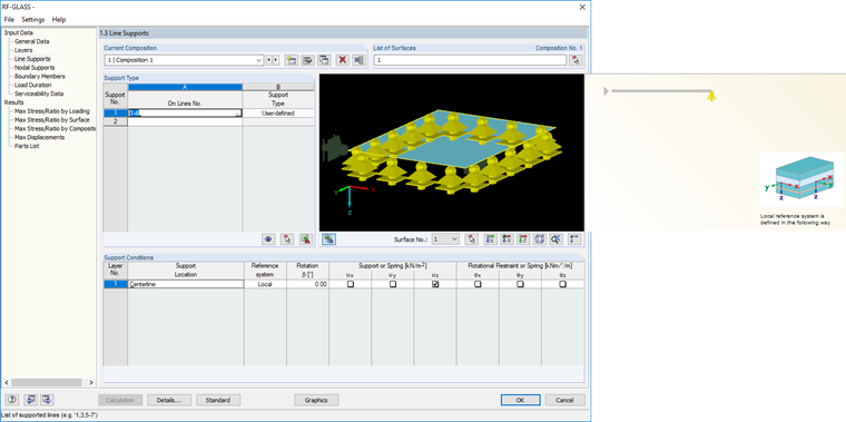
If the calculation is based on the plate theory, it represents the simplest form for arranging supports. Supports are automatically assigned to the system line.
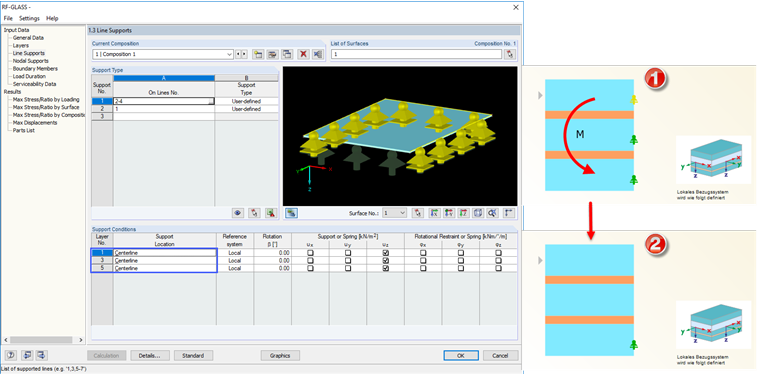
When you calculate according to the solid theory, however, several options are available. Supports can be defined on each glass layer, but this can lead to unwanted restraining moments in the support area. It is important to pay attention to this phenomenon when entering data, because this setting is not immediately apparent in the result evaluation.
Comparison of Results and Conclusion
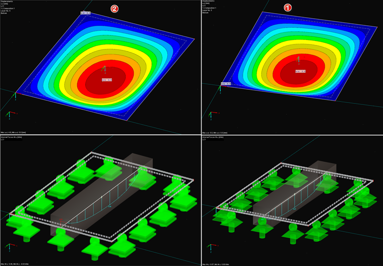
If you compare the results of both calculations of a simple laminated glass pane, supported on one edge and supported on all edges, it is clear that the design ratio of System 2 is even more favorable than with System 1. This is due to the fact that the support results in a restraint, which gives the support more stiffness, resulting in less deformation and lower internal forces in the center of the span.
However, this lower design ratio is a false conclusion, since the frame of the glass or the fastening of the glass pane to the frame is usually not designed for these forces. However, the results also show that the differences in the calculations are very small and, therefore, often go unnoticed. This article is thus intended to raise the user's awareness about constructing detail points before the calculation, especially in glass construction, in order to be able to design the model as precisely as possible in the FE program.