


Punching Shear Design Without Enlarged Column Head
If a punching shear design is performed at a point-supported load application location, this is done in RF-PUNCH Pro without applying an enlarged column head.
The add-on module tries to fulfill the design by automatically increasing the longitudinal reinforcement content. If the automatically increased longitudinal reinforcement content is too low, a punching shear reinforcement is automatically arranged.
Optionally, you can also specify a defined longitudinal reinforcement ratio (input in [cm²/m]). If the punching shear resistance is not sufficient when specifying this longitudinal reinforcement, the program also starts automatically with the arrangement of shear reinforcement. See Image 01 with a point-supported floor in RF-PUNCH Pro.
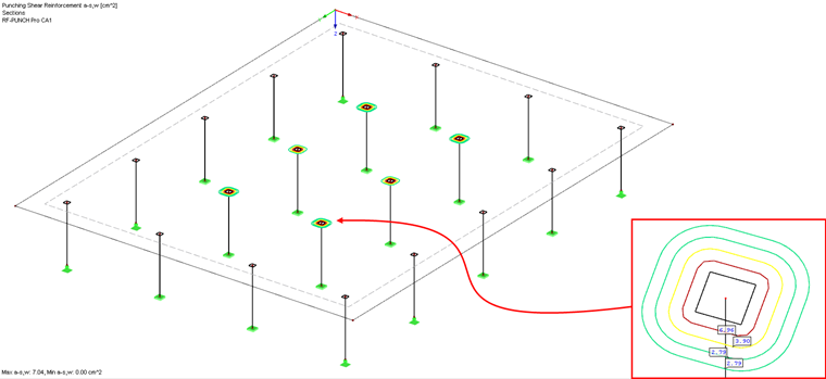
RF-PUNCH Pro has increased the longitudinal and punching shear reinforcement at the punching locations, where necessary.
Read more about the punching shear design without an enlarged column head in this technical article.
KB 001389 | Punching Shear Design According to Eurocode 2 in RFEM
Entering Enlarged Column Head
By arranging an enlarged column head, you can increase the punching resistance because it increases the static depth d at a distance of 2 d from the edge of the load introduction (column). This way, it is possible to completely avoid a shear reinforcement or to achieve a smaller degree of the required longitudinal reinforcement.
Activate the enlarged column head in the input dialog box "1.5 Nodes of Punching Shear".
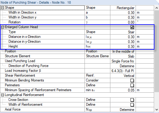
RF-PUNCH Pro provides the enlarged column head types "Stairway" and "Cone".
The dimensions lH,x and lH,y describe the distance from the front edge of the column to the front edge of the enlarged column head. The height hH corresponds to the height of the enlarged column head (without the slab component). These parameters are also described in Figures 6.17 and 6.18 in [1] as well as in Figures 3.36 and 3.37 in the RF-PUNCH Pro manual [2].
If one of the mentioned dimensions is changed, it is displayed in the interactive infographic in the right part of input dialog box 1.5.
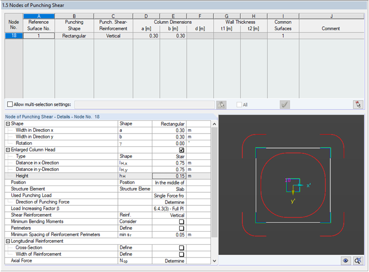
In Image 03, the dimension of the enlarged column head with
- lH,x = 0.75 m
- lH,y = 0.75 m
- hH = 0.15 m
was selected in such a way that the punching shear design has to be performed once within the enlarged column head, and once outside the enlarged column head or in the area of the actual slab.
In this case, the add-on module displays the control perimeters (lH ≥ 2hH ) as continuous lines.
As an alternative to this case, the case lH <2hH may occur if the following dimensions are entered, for example:
- lH,x = 0.40 m
- lH,y = 0.40 m
- hH = 0.35 m
In this case (lH < 2hH), the enlarged column head is so compact that the punching cone cannot completely form within the enlarged column head, so only the punching in the slab area will be designed. The add-on module displays the critical perimeter for punching "within" the enlarged column head as a dotted line.
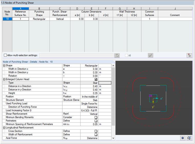
This situation is shown in Figure 6.17 in [1].
Calculation and Display of Results
If an enlarged column head is applied and the punching within the enlarged column head is analyzed (lH ≥ 2hH), RF-PUNCH Pro provides the user with a result row after the calculation for punching in the area of the slab and a result row for punching within the enlarged column head in the "2.1 Punching Shear Design" dialog box.
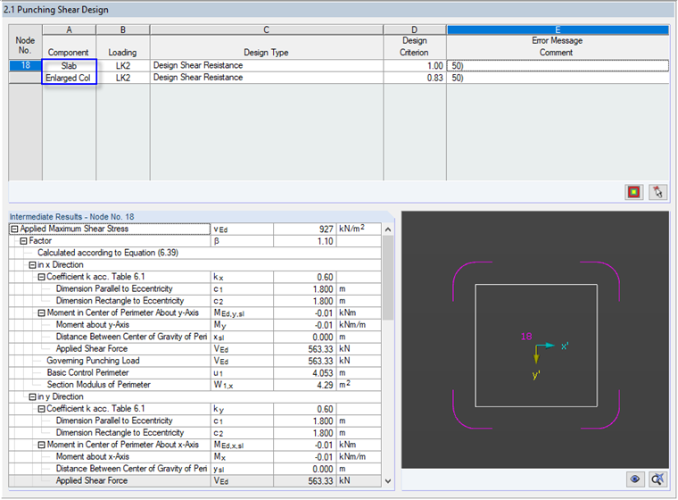
The add-on module shows the punching in the area of the slab with the load surface "Enlarged column head". Punching in the area of the enlarged column head is determined with the load surface "Column".
If only the punching shear design is performed outside the enlarged column head, the output of the results does not differ from a design without an enlarged column head.
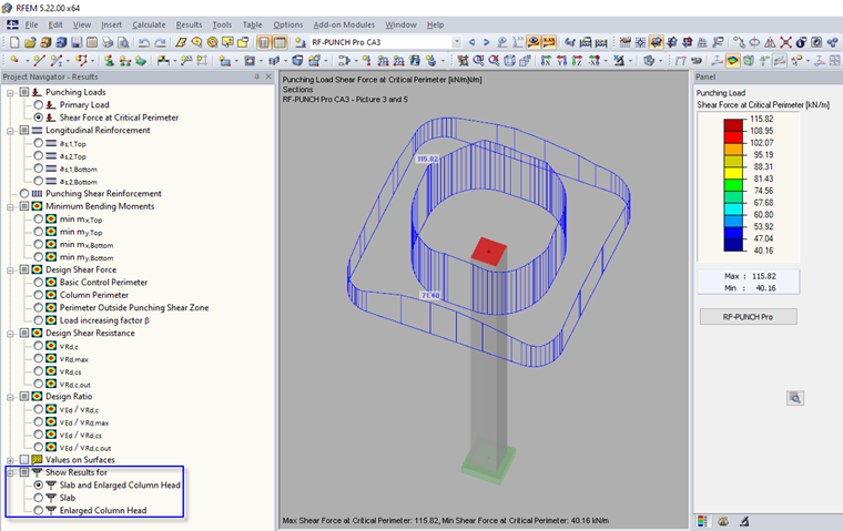
When graphically evaluating the design results, it is possible to distinguish between the results for the slab and/or the enlarged column head in the Results Navigator. Figure 06 shows the shear forces distribution in the critical perimeter for "Plate and Enlarged Column Head".
Notes on Modeling
The enlarged column head considered in RF-PUNCH Pro does not have to be considered for the modeling in the RFEM model. In the RFEM model, the "standard case" of the slab is represented without considering a reinforcement. The module determines the thickness of the enlarged column head from the thickness of the surface connected to the nodes and the entered thickness of the enlarged column head hH.
Due to this procedure, the enlarged column head has no influence on the stiffness or the results from the determination of internal forces in RFEM. The additional self-weight of the enlarged column head is also neglected with this option.
Selecting the enlarged column head in input dialog box 1.5 is only possible when connecting a single column to a surface.
