With the model shown here, you can design connections under realistic loadings quickly. In order to be able to verify the model with the DSTV guideline of typified connections [1], we selected the following system.
Structural System
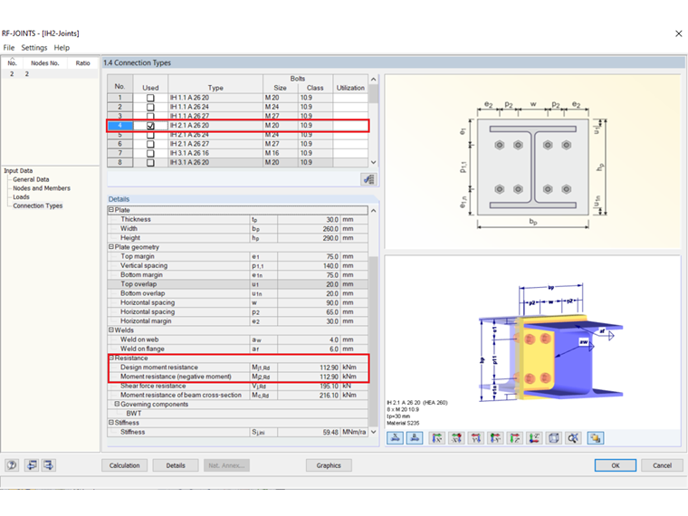
- Typified connection: IH 2.1 A 26 20
- Cross-section: HEA 260
- Material: Steel S235
- Bolts: M20 of strength class 10.9
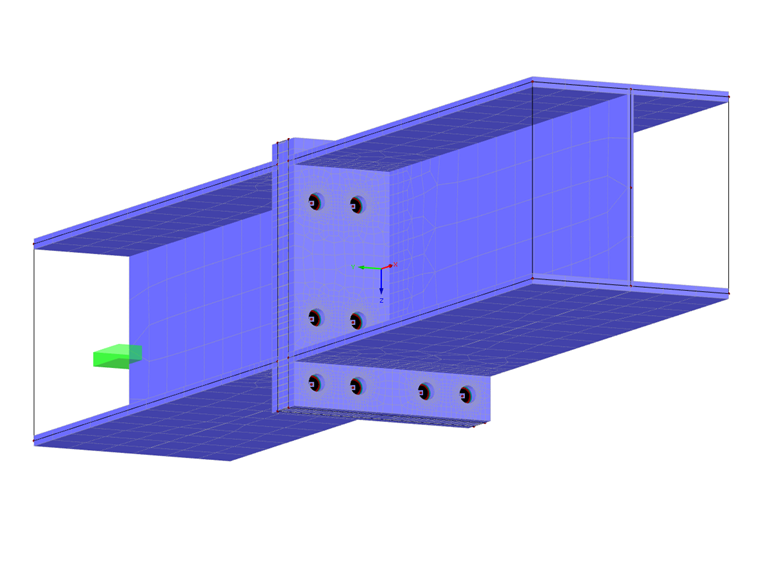
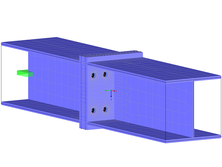
The FE model is created by means of surface elements for the beam. The modeling of the end plate is carried out by surfaces, which are then connected to each other in order to create a contact solid between them. It defines the exact contact properties between the two surfaces. In this specific case, there is a failure in the case of a vertical tensile stress. S235 steel is also selected as the material for the two end plate surfaces, but with plastic material behavior. Openings are modeled in the surfaces to represent the holes.
The screws of the connection are defined as tension members and are shown in simplified form without a nut. A tension member only has a longitudinal stiffness E ⋅ A and can only absorb tensile forces. Moment hinges are arranged at the member ends. The screws are connected in a simplified way by several rigid members with member end hinges on the respective end plate. By entering the desired bolt size, all calculation-relevant parameters of the bolts (strength class 10.9) are transferred. Thus, it is possible to imply the correct strain length as a formula in the model in order to obtain the most accurate bolt forces.
Application
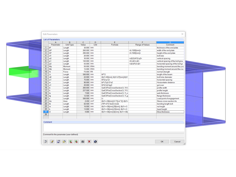
After opening the model, you can adjust the cross-section in the Data Navigator. The model is parameterized for the HEA, HEB, and HEM beams standardized according to DIN EN 1025. You can then display the parameters and enter the dimensions and thickness of the end plate. Enter the bolt size (M12, M16, M20, M22, M24, M27, M30, M36) and the desired bolt spacings. At the same time, all screw parameters that are important for the calculations are adjusted. Finally, it is possible to adjust the loads.
Design
To determine the load-bearing capacity of the connection, an initial load My of 50 kNm is applied and calculated with the load increment method. Then, you can evaluate the bolt forces and the plastic strains. To do this, you have to determine the maximum tension resistance as follows.
|
k2 |
Faktor der Zugfähigkeit [-] |
|
fub |
Zugfähigkeit Schraubenmaterial [N/mm²] |
|
As |
Spannungsquerschnitt [mm²] |
|
γM2 |
Teilsicherheitsbeiwert der Schraube [-] |
Evaluation and Comparison
When comparing the tension resistance to the bolt forces of the FE modeling, you can see that failure of the bolts occurs if the load is increased more than 2.1 times. The bolt forces are 175.4 kN with an acting moment of 105 kNm.
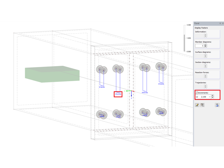
Thus, the load-bearing capacity of the connection of 105 kNm results from 2.1 ⋅ 50 kNm.
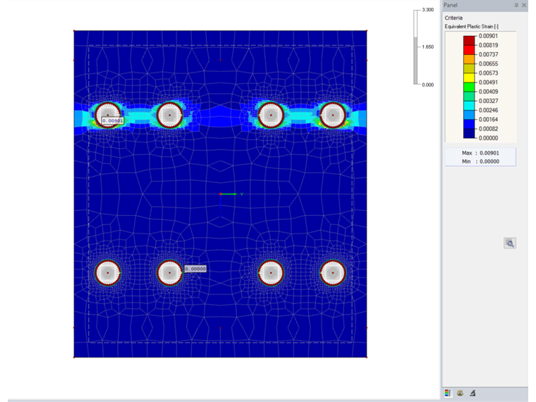
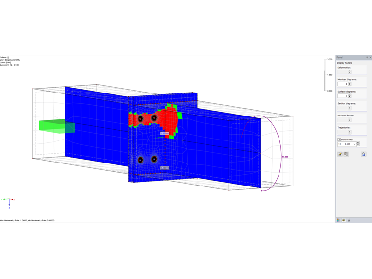
Evaluating the plastic strains shows maximum values of approximately one percent, which does not exceed the allowable limit strain of five percent according to EC3. In addition, you can see when the material starts to yield when displaying the nonlinearity degrees.
The DSTV guideline [1] gives a load capacity of 112.9 kNm, which differs only slightly from the created FE model.
This deviation reflects, among other things, the lack of modeling of the welds, which results in a lower stiffness of the outer bolt row. As a result, the internal screws are subjected to more loading and thus tend to fail.
Below, you can also download a model showing a connection with an extending end plate.