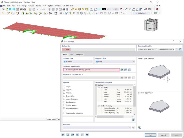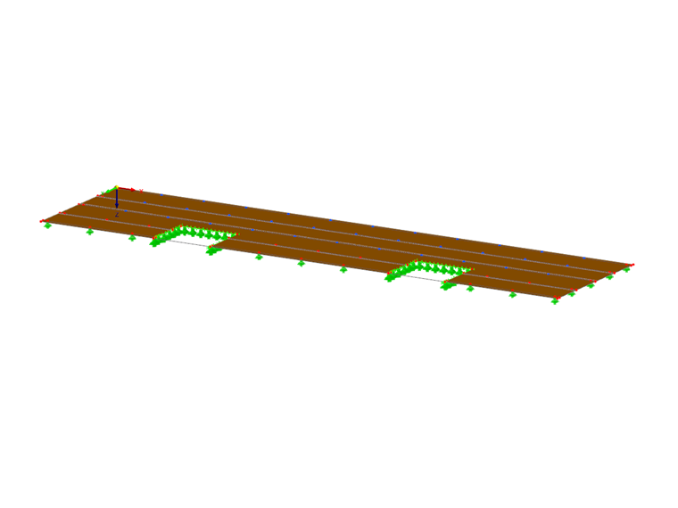
This add-on is appropriate for the calculation of cross-laminated timber, glass surfaces (laminated and insulating glass), and fiber-reinforced plastic composites. Furthermore, you can use it to calculate layer elements in concrete, lightweight, or element structures. In this article, the add-on will be employed to define the thickness of the multilayer surfaces that form the slab shown in Image 2.
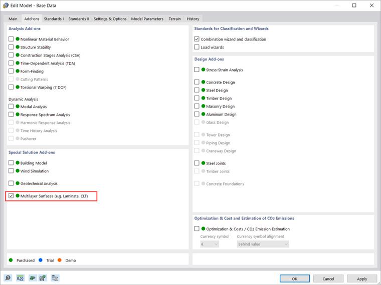
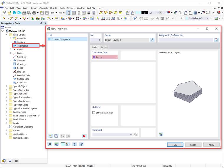
In RFEM 6, you can define layers in the “New Thickness” dialog box (accessible via the Data navigator and the “Insert” menu). When the “Multilayer Surfaces” add-on is active, “Layers” is available for selection as the thickness type (Image 3).
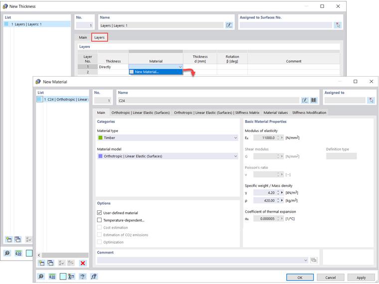
By selecting “Layers” as the thickness type, an associated tab is available to define layers in terms of material, thickness, and rotation (Image 4). You can define the material of the individual layers by choosing “New Material” and select the material from the RFEM library, or by defining the material properties yourself.
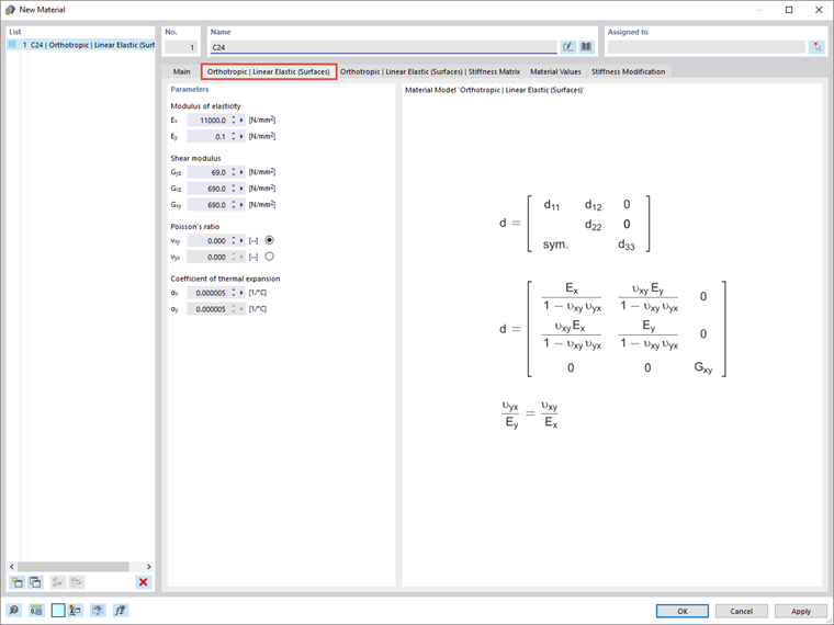
In this example, the material of the first layer is “Timber”, the material model is set as “Orthotropic | Linear Elastic (Surfaces)”, and the “User-defined material” option is activated. In this way, you can define the material parameters as shown in Image 5.
Once you have given the material parameters, you can define the thickness (d) of the layer and the rotation angle β. The latter allows you to rotate the individual layer by an angle ß and thus consider different stiffnesses in one direction. For the first layer of the multilayer surface, no rotation is applied (that is, the rotation angle β is set to 0), and the thickness is set to 35 mm (Image 6).
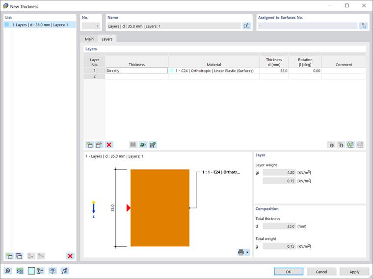
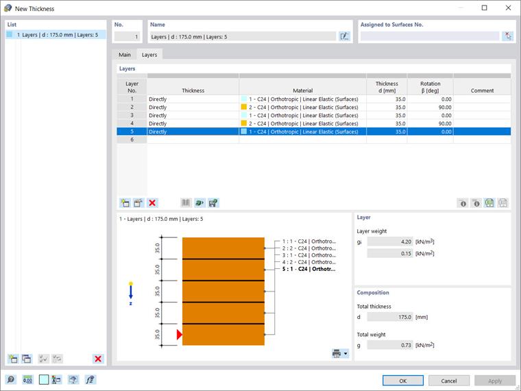
To define the total thickness, all you need to do is apply the same procedure for the remaining layers. The surface in this example consists of five layers with the same thickness defined as shown in Image 7. Please note that the data you enter in the table interact with the graphical display in the same tab, as well as with the automatic calculation of both the individual layer and the composition’s weight (Image 7).
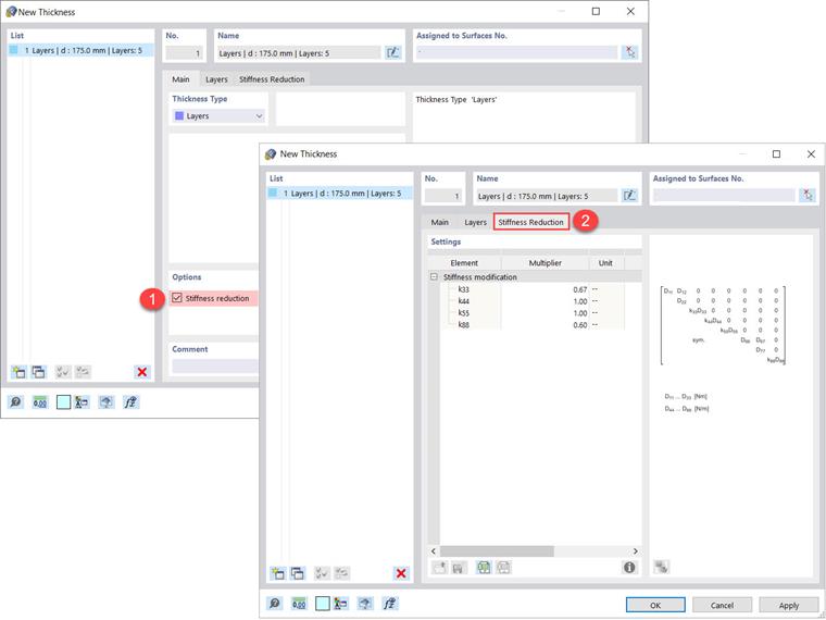
It is also possible to reduce stiffness when defining the thickness of the multilayer surface. You can find this option in the “Main” tab of the “New Thickness” window and activate it by ticking the corresponding checkbox. Then, you can introduce stiffness modifications as shown in Image 8.
This way, you can consider the fact that cross-laminated timber is generally not glued at the narrow side and thus, no shear stresses can be transferred to the narrow sides of the timber. You can take this into account by adjusting the k33 and k88 factors, thus reducing torsional stiffness D33 and shear stiffness D88, respectively, of the corresponding stiffness matrix.
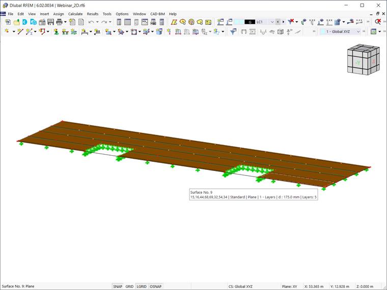
Once you have defined the thickness of interest, you can assign it to the surfaces you need to create (Image 9) and obtain the slab made of multilayer surfaces shown at the very beginning of this text (Image 2).