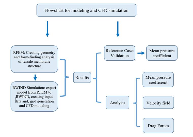
RFEM and RWIND are used to generate a tensile membrane structure model so that wind simulation can be started, along with the implementation of important criteria. RWIND is a powerful tool for creating wind loads on general structures and complicated forms. CFD solver is an OpenFOAM® software package (version 17.10), which gives very good results and is a widely used tool for CFD simulations. The numerical solver is steady-state for incompressible, turbulent flow, using the SIMPLE (Semi-Implicit Method for Pressure Linked Equations) algorithm.
The wind loads are regulated by specific standards, such as EN 1991-1-4, ASCE/SEI 7-16, or NBC 2015. RFEM is well-equipped technical software for creating tensile membrane structures; it considers nonlinear form-finding analysis for prestressed double-curvature surfaces. Image 02 presents a numerical airflow flowchart and FEM modeling for performing a verification example regarding tensile membrane structures.
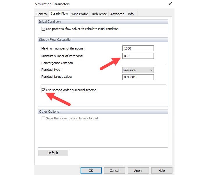
In order to determine partial differential equations numerically, all differential expressions (space and time derivatives) need to be discretized. There is a wide range of discretization methods with different approaches in terms of accuracy, stability, and convergence. Generally, the order of the discretization illustrates how accurate the numerical simulation is when compared to the solutions of the original non-discretized equations. The first-order numerical discretization basically generates better convergence than the second-order scheme. In the current study, second-order discretization is used. Also, when using the second-order numerical scheme, we recommend increasing the minimum number of iterations to achieve better convergence (Image 03).
Verification Example
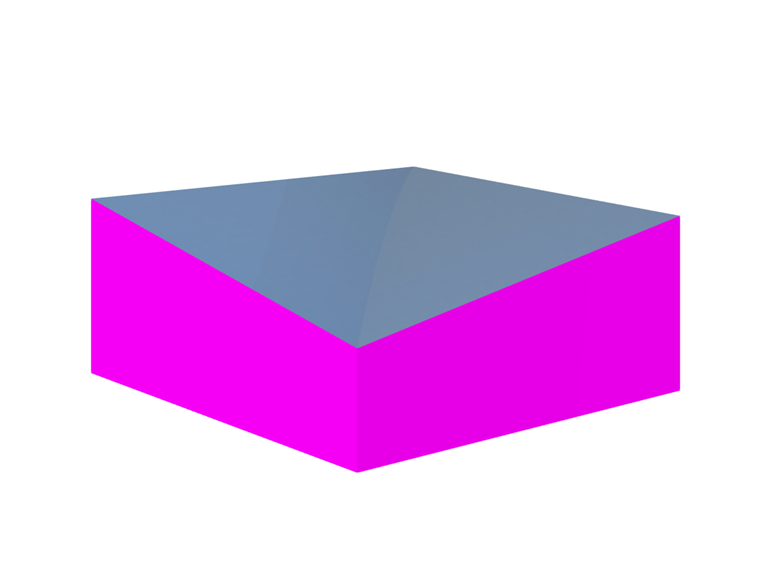
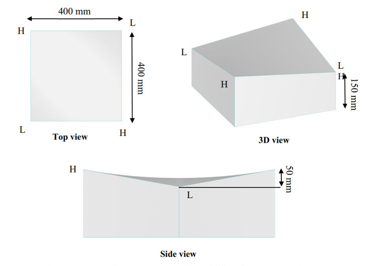
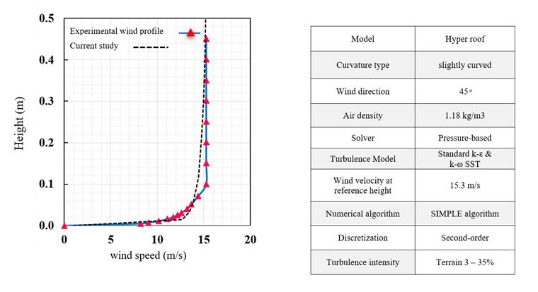
To verify the process for wind simulation, a double curvature model is developed as shown in [1] [2], and the results are investigated. The scale of the slight curve model is selected as 1/25, which is the same as the experimental model in reference [3], illustrating a hypar roof 10 m by 10 m by 1.25 m. The slight curve is considered for verifying an example with an angle θ=45o. The pretension force for the real scale was applied 2.5 kN/m on the surface, and mechanical properties such as Young's modulus and Poisson's ratio are defined as Ex=1000 kN/m. Ey=800 kN/m. Gxy=100 kN/m, vxy=0.20. Image 04 illustrates the geometry of the double curvature model. The input information and wind velocity input for CFD simulation are shown in Image 05.
Wind Tunnel Dimension
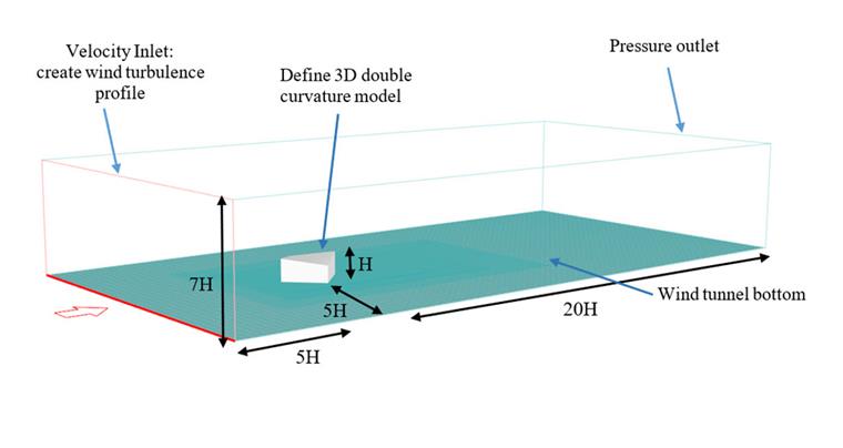
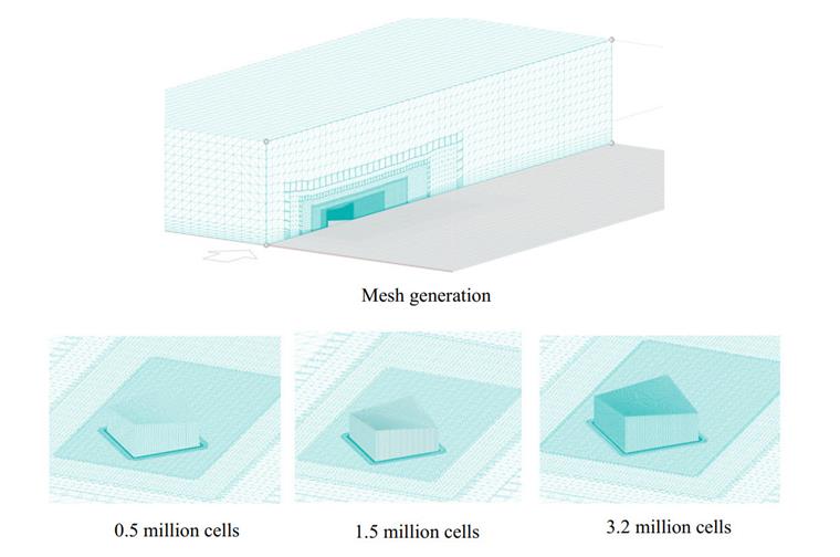
It is important to note that the wind tunnel dimension can produce errors if the tunnel size is smaller than the standard type. The following image shows a standard dimension of a wind tunnel [3]. Also, the results are sensitive to mesh sizes, so the calculation should perform for at least three different mesh numbers, and when the results are close enough to the previous stage, grid independence is achieved (Image 06).
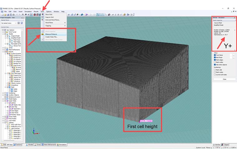
A side view of the mesh generation of the model is presented in Image 07; as can be seen, the algorithm of mesh refinement is employed at a close distance to the model surface.
Computational Grid Study
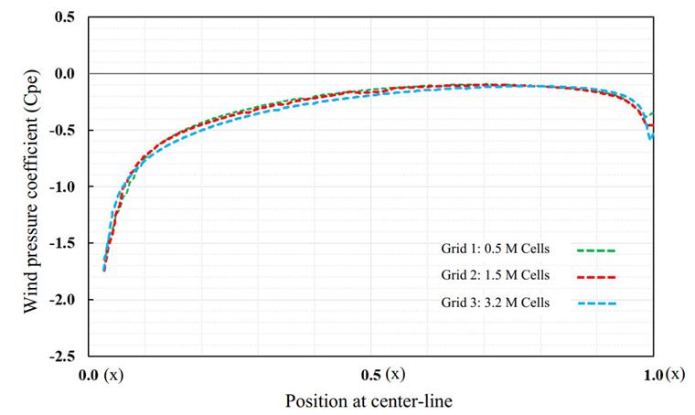
The results in CFD simulation are sensitive to mesh size, so grid independence should be performed for at least three different numbers of mesh elements. Here are the results of the Cp-value on the roof center line; as can be seen, there are very slight differences that show the results of wind simulation become independent of the third grid (Image 08).
Blended Wall Function
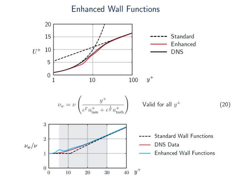
RWIND uses the Blended Wall Function (BWF), also known as Enhanced Wall Function (EWF), which shows much better performance than the Standard Wall Function (SWF). Thus, generally, you can be sure that you will receive accurate results for the wide range of y+ numbers. The BWF is not a symmetric function. We have a solid black line (as shown in image 09), which is the Direct Numerical Simulation (DNS) that we are trying to reproduce. What you can see straight away is that the EWF is definitely much closer to the DNS data than the SWF. Thus, in the buffer region between a y+ of 5 and 30, the EWF is definitely much more accurate compared to the SWF. This is why EWF is often recommended in CFD simulations [4]. However, it's important to emphasize that RWIND is not intended for detailed boundary layer investigations involving low y+ values. RWIND is designed as a fast, approximate, practical solution tailored for civil engineers who may not have extensive CFD expertise and are interested in performing industrial projects.
The mean pressure diagram and contour for the two turbulence models are shown in Images 10 and 11. Based on the center line of the hypar roof, the diagram of Cpe distribution is plotted and compared with the experimental wind tunnel test. The Cp value can be driven by the following equation, where P is the wind pressure at the measured point, Pref the reference pressure (atmosphere pressure), ρ is the air density, and Uref the reference velocity equal to 15.3 m/s.
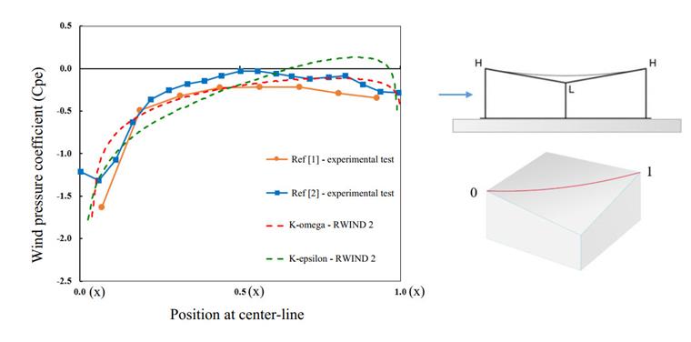
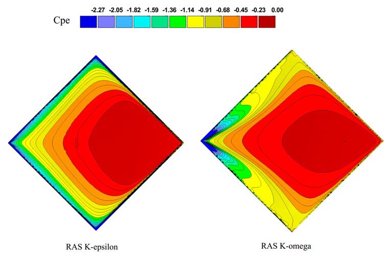
As shown here, the K-omega turbulence model shows better performance in predicting the wind pressure coefficient; in the current study, the K-omega turbulence model captures the effects of vortex shedding in high gradient negative wind pressure better than the K-epsilon models. We recommend using this turbulence model as a more accurate option in wind-structure interactions.