
In this example, the shear at the interface between concrete cast at different times and the corresponding reinforcement are determined according to DIN EN 1992-1-1. The obtained results with RFEM 6 will be compared to the hand calculation below.

In this verification example, the capacity design values of shear forces on beams are calculated in accordance with EN 1998-1, 5.4.2.2 and 5.5.2.1 as well as the capacity design values of columns in flexure in accordance with 5.2.3.3(2). The system consists of a two span reinforced concrete beam with a span length of 5.50m. The beam is part of a frame system. The results obtained are compared with those in [1].

An inner column in the first floor of a three-story building is designed. The column is monolithic connected with the top and bottom beams. The fire design simplified method A for columns according to EC2-1-2 is than proofed and the results compared to [1].
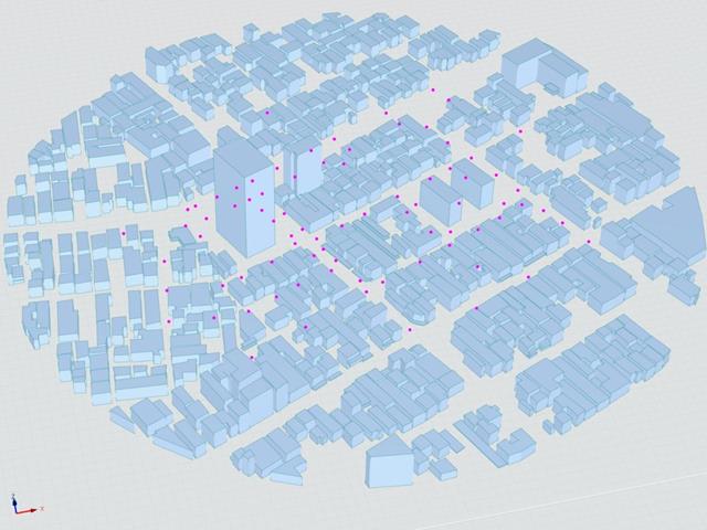
The Architectural Institute of Japan (AIJ) has presented a number of well-known benchmark scenarios of wind simulation.
The following article deals with "Case E - Building Complex in Actual Urban Area with Dense Concentration of Low-Rise Buildings in Niigata City".
In the following, the described scenario is simulated in RWIND& 2 and the results are compared with the simulated and experimental results by AIJ.
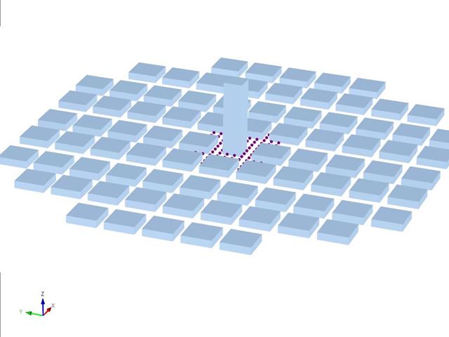
The Architectural Institute of Japan (AIJ) has presented a number of well-known benchmark scenarios of wind simulation.
The following article deals with "Case D - High-Rise Building Among City Blocks".
In the following, the described scenario is simulated in RWIND 2 and the results are compared with the simulated and experimental results by the AIJ.
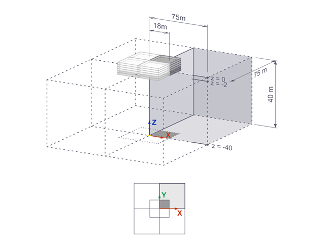
The settlements of a rigid square foundation on a lacustrine clay [1] are calculated with RFEM. One quarter of the foundation is modelled. The foundation has a width of 75.0 m in both sides. Construction stages are used to generate the results.
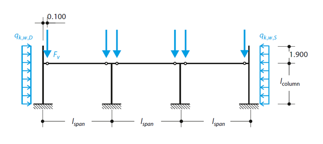
A reinforced concrete column is designed for ULS at normal temperature according to DIN EN 1992-1-1/NA/A1:2015, based on 1990-1-1/NA/A1:2012-08. The design employs the nominal curvature method; see DIN EN 1992-1-1, Section 5.8.8. The addressed column is located at the edge of a 3-span frame structure, which consists of 4 cantilever columns and 3 individual trusses hinged to them. The column is subjected to the vertical force of the precast truss, snow and wind. The results are compared with the literature.
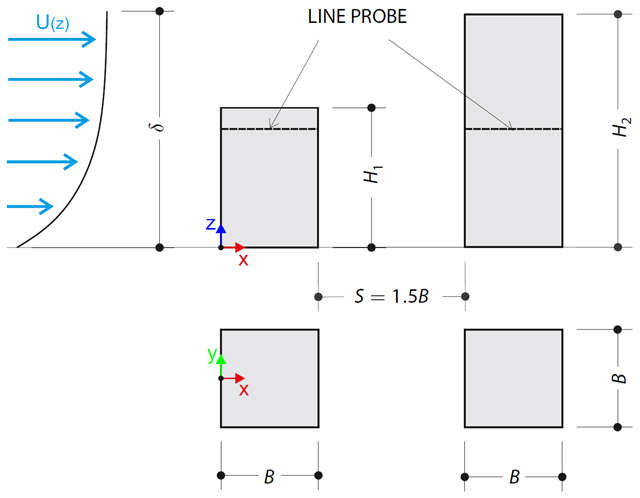
The verification example describes pressure loads on the walls of buildings in tandem arrangement located at ground level. The buildings are simplified to rectangular objects and scaled down while maintaining the elevation ratios. The pressure distribution on the walls of the model of a medium-high building was conducted by an experiment. The chosen results (pressure coefficient Cp) are compared with the measured values.
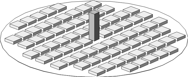
The verification example describes the steady-state flow around a high-rise building in city blocks (scaled model). The example is given by the Architectural Institute of Japan (AIJ). The chosen results (velocity magnitude) are compared with the measured values.
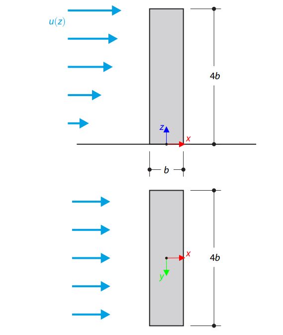
The verification example describes the steady-state flow around an isolated building (scaled model).The example is given by the Architectural Institute of Japan (AIJ). The chosen results (velocity magnitude) are compared with the measured values.
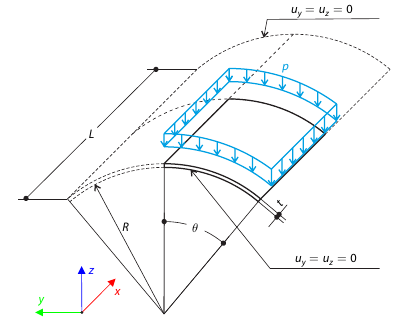
A shell roof structure under pressure load is modeled where the straight edges are free, while at the curved edges the y- and z‑translations are constrained. Neglecting self‑weight, compute the maximum (absolute) vertical deflection, and compare the results with COMSOL Multiphysics 4.3.
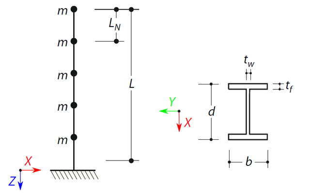
A cantilever beam with an I-beam cross-section of length L is defined. The beam has five mass points with masses m acting in the X-direction. The self-weight is neglected. The frequencies, mode shapes, and equivalent loads of this 5-DOF system are analytically calculated and compared with the results from RSTAB and RFEM.
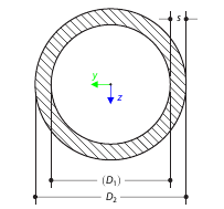
Determine the torsional constant for the cross-section of the tube (annular area) analytically, and compare the results with the numerical solution in RFEM 5 and RSTAB 8 for various wall thicknesses.
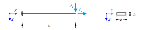
Prove that coupling different dimensional elements does not affect the results. A cantilever with a rectangular cross-section is fixed at one end and loaded at the other by concentrated forces. Neglecting its self-weight and assuming only small deformations, determine the cantilever's maximum deflections.