
In this example, the shear at the interface between concrete cast at different times and the corresponding reinforcement are determined according to DIN EN 1992-1-1. The obtained results with RFEM 6 will be compared to the hand calculation below.

A reinforced concrete beam is designed as a two-span beam with a cantilever. The cross-section varies along the length of the cantilever (tapered cross-section). The internal forces, the required longitudinal and shear reinforcement for the ultimate limit state are calculated.

The model is based on the example 4 of [1]: Point-supported slab.
The flat slab of an office building with crack-sensitive lightweight walls is to be designed. Inner, border and corner panels are to be investigated. The columns and the flat slab are monolithically joined. The edge and corner columns are placed flush with the edge of the slab. The axes of the columns form a square grid. It is a rigid system (building stiffened with shear walls).
The office building has 5 floors with a floor height of 3.000 m. The environmental conditions to be assumed are defined as "closed interior spaces". There are predominantly static actions.
The focus of this example is to determine the slab moments and the required reinforcement above the columns under full load.
The model is based on the example 4 of [1]: Point-supported slab. The internal forces and the required longitudinal reinforcement can be found the in verification example 1022. In this example, punching is examined in the axis B/2.
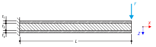
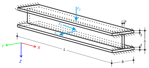
A sandwich cantilever consists of three layers (the core and two faces). It is fixed on the left end and loaded by a concentrated force on the right end.
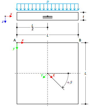
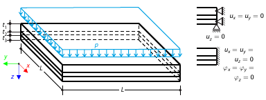
One layered square orthotropic plate is fully fixed at its middle point and subjected to pressure. Compare the deflections of the plate corners to check the correctness of the transformation.
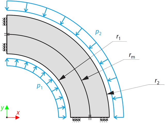
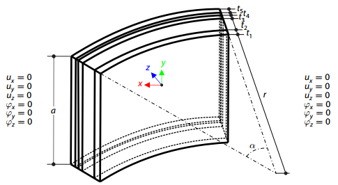
A two-layered, open-ended, thick-walled vessel is loaded by inner and outer pressure; therefore, there is no axial stress. While neglecting self‑weight, the radial deflection of the inner and outer radius, and the pressure (radial stress) in the middle radius is determined.
A composite plate consisting of three glass layers, one foil layer, and an inner space with dry air, is fully fixed and loaded with a variable temperature. Neglecting its self-weight, determine the plate's maximum deflection.
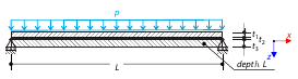
Determine the maximum displacement, in-plane stresses, and stress ratios of a simply supported double-pane glass plate with a foil between both glass panes subjected to uniform pressure.
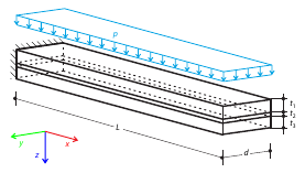
Determine the maximum deflection of the cantilever consisting of two glass layers and one foil layer in between. The plate is fully fixed at one end and subjected to uniform pressure.
One layered square orthotropic plate is fully fixed at its middle point and subjected to pressure. Compare the deflections of the plate corners to check the correctness of the transformation.
Determine the maximum deflection and stress in the z-direction of the composite plate, consisting of two glass layers and one foil layer in between, subjected to uniform pressure.