Kelvin-Voigt material model consists of the linear spring and viscous damper connected in parallel. In this verification example there is tested the time behaviour of this model during the loading and relaxation in a time interval 24 hours. The constant force Fx is applied for 12 hours and the rest 12 hours is the material model free of load (relaxation). The deformation after 12 and 20 hours is evaluated. Time History Analysis with Linear Implicit Newmark method is used.
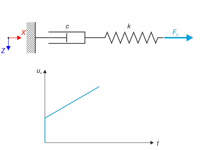
Maxwell material model consists of the linear spring and viscous damper connected in series. In this verification example there is tested the time behaviour of this model. The Maxwell material model is loaded by constant force Fx. This force causes initial deformation thanks to the spring, the deformation is then growing in time due to the damper. The deformation is observed at time of loading (20 s) and at the end of the analysis (120 s). Time History Analysis with Linear Implicit Newmark method is used.
A cantilever is loaded by a moment at its free end. Using the geometrically linear analysis and large deformation analysis, and neglecting the beam's self-weight, determine the maximum deflections at the free end. The verification example is based on the example introduced by Gensichen and Lumpe.
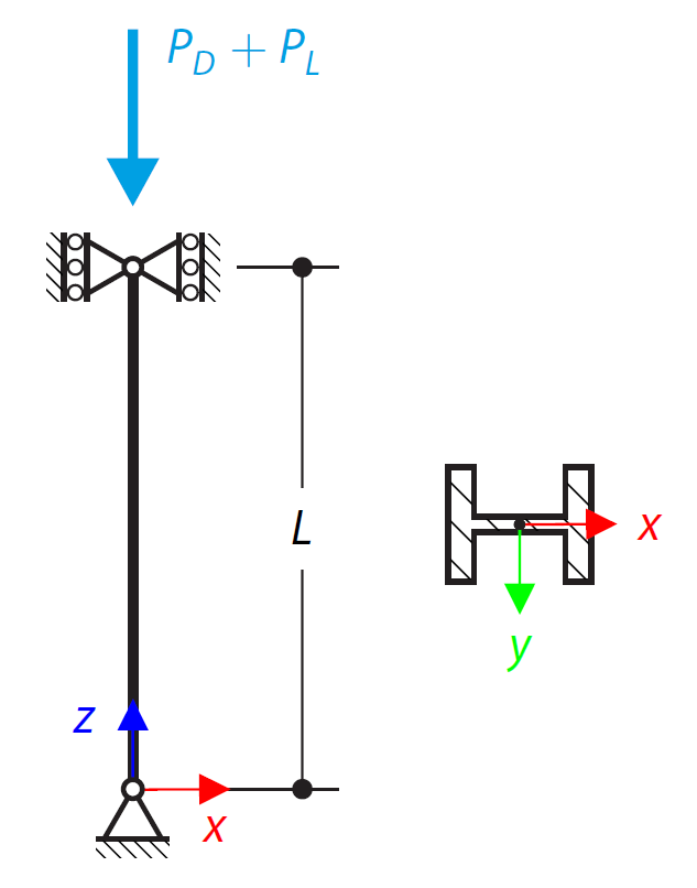
An ASTM A992 14×132 W-shaped column is loaded with the given axial compression forces. The column is pinned top and bottom in both axes. Determine whether the column is adequate to support the loading shown in Figure 1 based on LRFD and ASD.
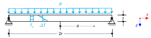
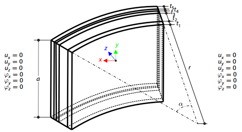
Determine the maximum deflection and maximum radial moment of a simply supported circular plate subjected to uniform pressure, uniform temperature, and differential temperature.
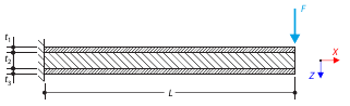
A sandwich cantilever consists of three layers (the core and two faces). It is fixed on the left end and loaded by a concentrated force on the right end.
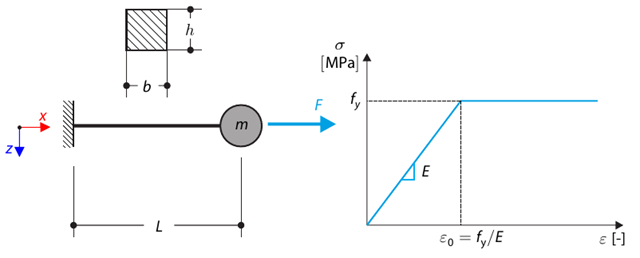
This verification example is based on Verification Example 0122. A single-mass system without damping is subjected to an axial loading force. An ideal elastic-plastic material with characteristics is assumed. Determine the time course of the end-point deflection, velocity, and acceleration.
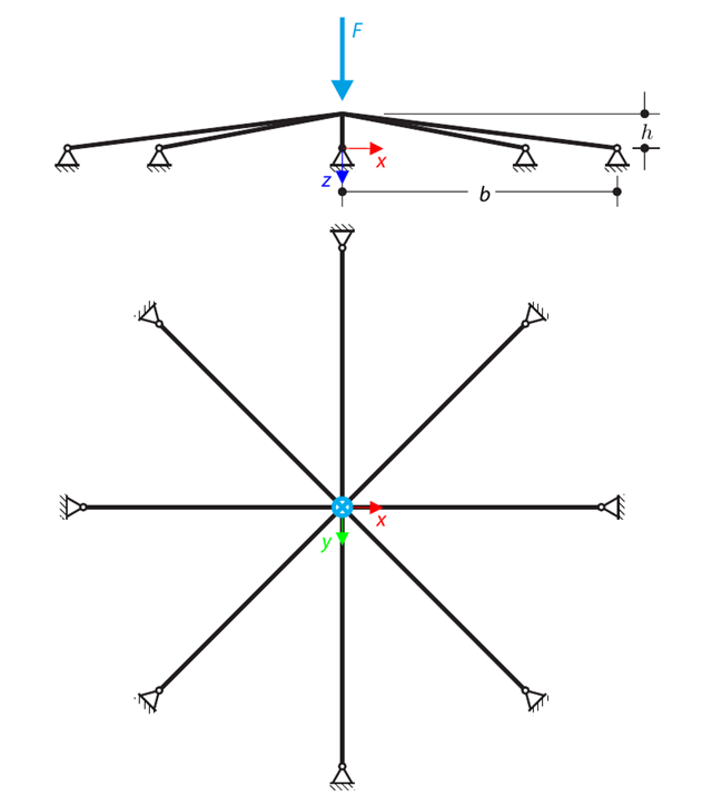
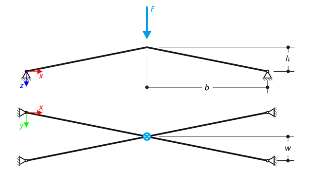
A symmetrical shallow structure is made of eight equal truss members, which are embedded into hinge supports. The structure is loaded by a concentrated force and alternatively by imposed nodal deformation over the critical limit point when the snap-through occurs. Imposed nodal deformation is used in RFEM 5 and RSTAB 8 to obtain the full equilibrium path of the snap-through. The self-weight is neglected in this example. Determine the relationship between the actual loading force and the deflection, considering large deformation analysis. Evaluate the load factor at the given deflections.
A structure is made of four truss members, which are embedded into hinge supports. The structure is loaded by a concentrated force and alternatively by imposed nodal deformation over the critical limit point, when snap-through occurs. Imposed nodal deformation is used in RFEM 5 and RSTAB 8 to obtain the full equilibrium path of the snap-through. The self-weight is neglected in this example. Determine the relationship between the actual loading force and the deflection, considering large deformation analysis. Evaluate the load factor at given deflections.
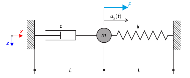
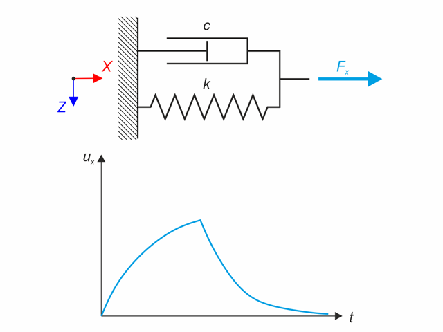
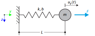
A single-mass system with dashpot is subjected to a constant loading force. Determine the spring force, damping force, and inertial force at the given test time. In this verification example, the Kelvin--Voigt dashpot (namely, a spring and a damper element in serial connection) is decomposed into its purely viscous and purely elastic parts, in order to better evaluate the reaction forces.
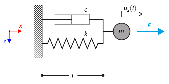
A single-mass system with dashpot is subjected to constant loading force. Determine the deflection and velocity of the dashpot endpoint in the given test time.
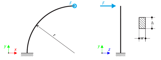
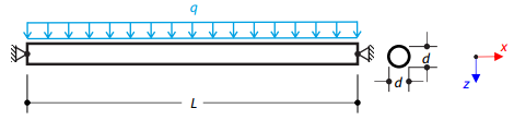
A quarter-circle beam with a rectangular cross-section is loaded by means of an out-of-plane force. This force causes a bending moment, torsional moment, and transverse force. While neglecting self-weight, determine the total deflection of the curved beam.
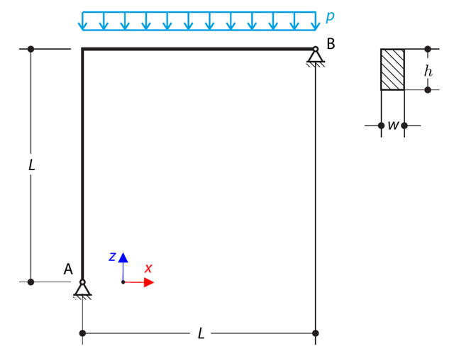
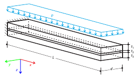
A curved beam consists of two beams with a rectangular cross-section. The horizontal beam is loaded by distributed loading. While neglecting self-weight, determine the maximum stress on the top surface of the horizontal beam.
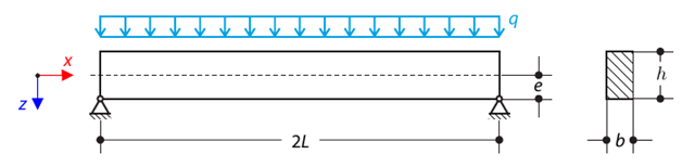
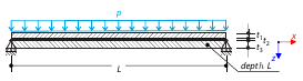
A pinned beam with a rectangular cross‑section is subjected to distributed loading and shifted vertically by eccentricity. Considering the small deformation theory, neglecting the self‑weight, and assuming that the beam is made of isotropic elastic material, determine the maximum deflection.
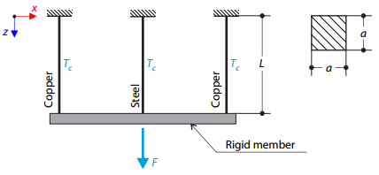
A truss structure consists of three rods (one steel and two copper) joined by a rigid member. The structure is loaded by a concentrated force and a temperature difference. While neglecting self‑weight, determine the total deflection of the structure.
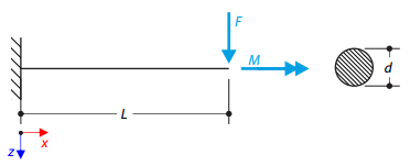
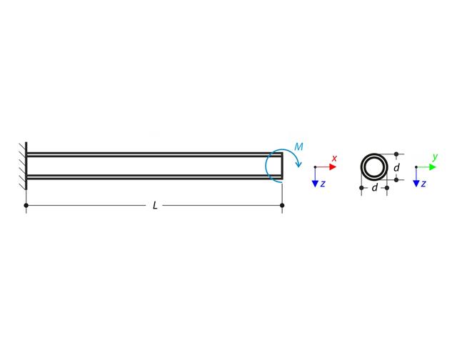
A cantilever with a circular cross‑section is loaded by a concentrated bending force and torque. The aim of this verification example is to compare the reduced stress according to the von Mises and Tresca theories.
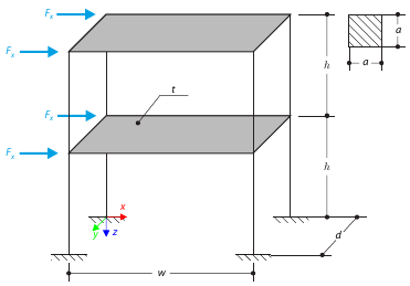
A two‑story, single‑bay frame structure is subjected to earthquake loading. The modulus of elasticity and cross‑section of the frame beams are much larger than those of the columns, so the beams can be considered rigid. The elastic response spectrum is given by the standard SIA 261/1:2003. Neglecting self-weight and assuming the lumped masses are at the floor levels, determine the natural frequencies of the structure. For each frequency obtained, specify the standardized displacements of the floors as well as equivalent forces generated using the elastic response spectrum according to the standard SIA 261/1.2003.
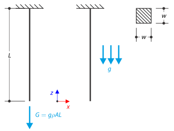
A rod with a square cross-section is fixed on the top end. The rod is loaded by self-weight. For comparison, the example is also modeled with the concentrated force load, the value of which is equal to the gravity. The aim of this verification example is to show the difference between these types of loading, although the total loading force is equal.
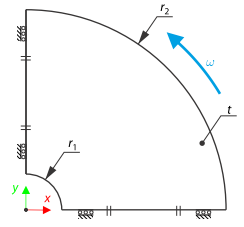
A compact disc (CD) rotates at a speed of 10,000 rpm. Therefore, it is subjected to centrifugal force. The problem is modeled as a quarter model. Determine the tangential stress on the inner and outer diameters and the radial deflection of the outer radius.
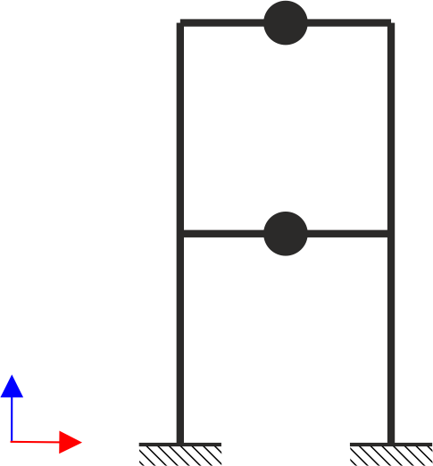
This example serves as a demonstration of the diaphragm constraint. The application is shown on a two-story structure. The structure is loaded by means of lateral forces according to Figure 1. Determine the maximum deflection of the structure ux in the direction of the loading forces using both the diaphragm constraint and the plate model of the floor.
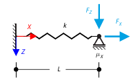
The goal of this example is to demonstrate an irreversible process caused by friction. After the loading and unloading, the end-point is in a different position than where it was at the beginning. Determine the movement of the node in the X direction.
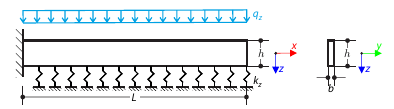
A cantilever from a rectangular cross-section is lying on an elastic Pasternak foundation and loaded by distributed loading. The image shows the calculation of the maximum deflection and maximum bending moment.
A composite plate consisting of three glass layers, one foil layer, and an inner space with dry air, is fully fixed and loaded with a variable temperature. Neglecting its self-weight, determine the plate's maximum deflection.
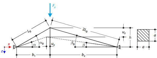
A structure is made of two trusses of unequal length, which are embedded into the hinge supports. The structure is loaded by concentrated force. The self-weight is neglected. Determine the relationship between the loading force and the deflection, considering large deformations.
A cantilever is loaded by a moment at its free end. Using the geometrically linear analysis and large deformation analysis, and neglecting the beam's self-weight, determine the maximum deflections at the free end. The verification example is based on the example introduced by Gensichen and Lumpe.
A single mass system is subjected to loading force. Determine the deflection of the system.
Determine the maximum displacement, in-plane stresses, and stress ratios of a simply supported double-pane glass plate with a foil between both glass panes subjected to uniform pressure.
Determine the maximum deflection of the cantilever consisting of two glass layers and one foil layer in between. The plate is fully fixed at one end and subjected to uniform pressure.
A steel cable or membrane with pins on both ends is loaded by distributed loading. Neglecting its self-weight, determine the maximum deflection of the structure using the large deformation analysis.
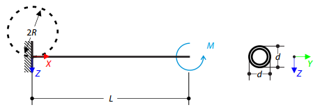
Determine the bending moment which, acting at the free end of the cantilever, will bend the member into a circular shape. Neglecting the beam's self-weight, assuming the large deformation analysis, and loading the cantilever with the moment, determine its maximum deflections.