
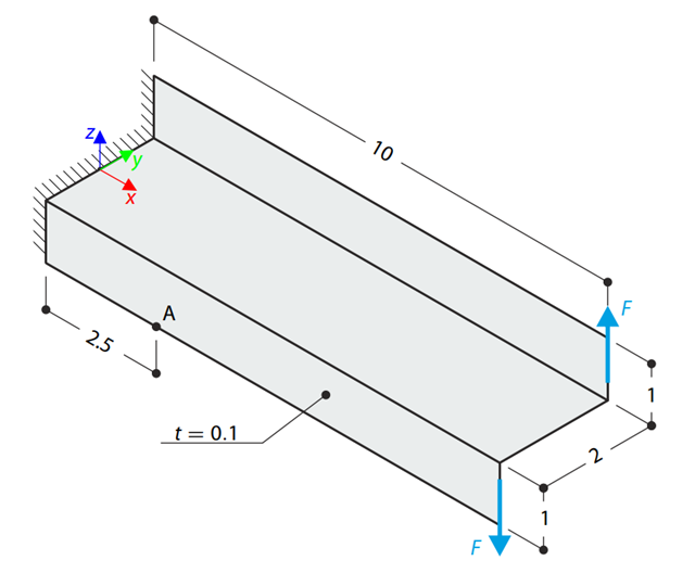
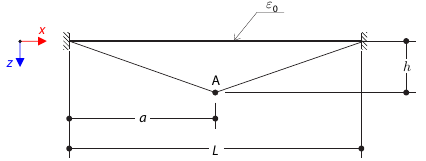
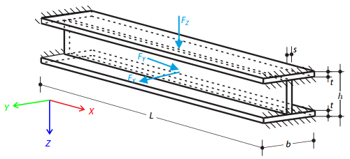
A structure is consisted of an I-section beam and two tube trusses. The structure contains several imperfections and it is loaded by the force Fz. The self-weight is neglected in this example. Determine the deflections uy and uz and axial rotation φx at the endpoint (Point 4). The verification example is based on the example introduced by Gensichen and Lumpe.
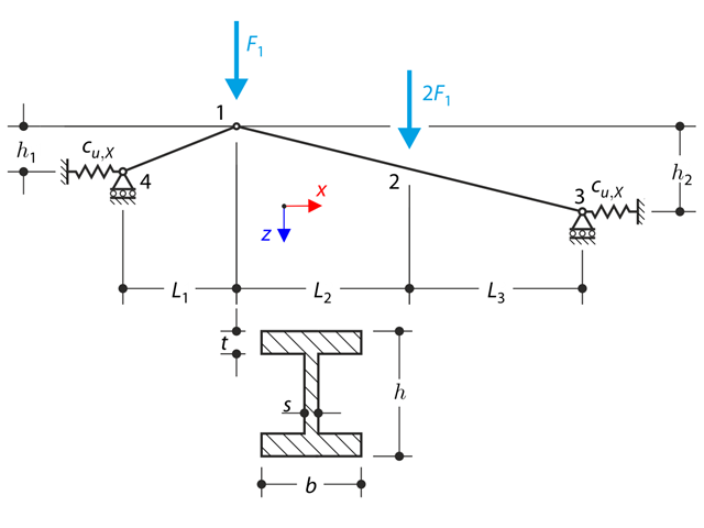
A structure made of I-profile trusses is supported on the both ends by the spring sliding supports and loaded by the transversal forces. The self-we ight is neglected in this example . Determine the deflection of the structure, the bending moment, the normal force in given test points and horizontal deflection of the spring support.

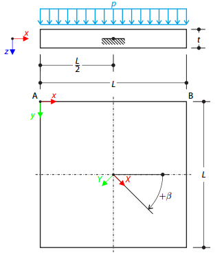
The model is based on the example 4 of [1]: Point-supported slab.
The flat slab of an office building with crack-sensitive lightweight walls is to be designed. Inner, border and corner panels are to be investigated. The columns and the flat slab are monolithically joined. The edge and corner columns are placed flush with the edge of the slab. The axes of the columns form a square grid. It is a rigid system (building stiffened with shear walls).
The office building has 5 floors with a floor height of 3.000 m. The environmental conditions to be assumed are defined as "closed interior spaces". There are predominantly static actions.
The focus of this example is to determine the slab moments and the required reinforcement above the columns under full load.
The model is based on the example 4 of [1]: Point-supported slab. The internal forces and the required longitudinal reinforcement can be found the in verification example 1022. In this example, punching is examined in the axis B/2.
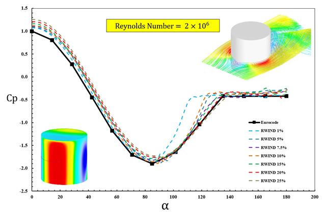
The available standards, such as EN 1991-1-4 [1], ASCE/SEI 7-16, and NBC 2015 presented wind load parameters such as wind pressure coefficient (Cp) for basic shapes. The important point is how to calculate wind load parameters faster and more accurately rather than working on time-consuming as well as sometimes complicated formulas in standards.
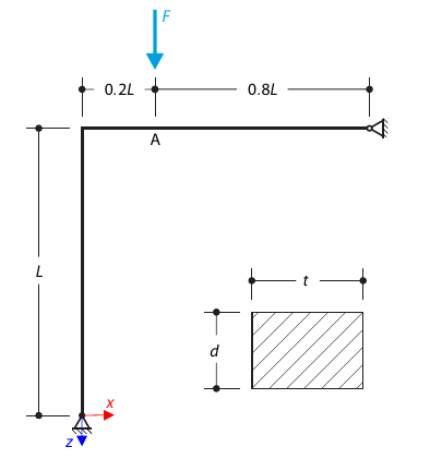
A curved frame called Lee's frame is pinned at the end points and loaded by a concentrated force at point A. Determine the deflection ratio at point A in the given load steps. The problem is defined according to The NAFEMS Non-Linear Benchmarks.
One layered square orthotropic plate is fully fixed at its middle point and subjected to pressure. Compare the deflections of the plate corners to check the correctness of the transformation.
A Z-Section Cantilever is fully fixed at the end and loaded by a torque which, in the case of a shell model, is represented by a couple of shear forces. Determine the axial stress at point A (at mid-surface). The problem is defined according to The Standard NAFEMS Benchmarks.
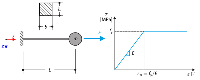
This verification example is based on Verification Example 0122. A single-mass system without damping is subjected to an axial loading force. An ideal elastic-plastic material with characteristics is assumed. Determine the time course of the end-point deflection, velocity, and acceleration.
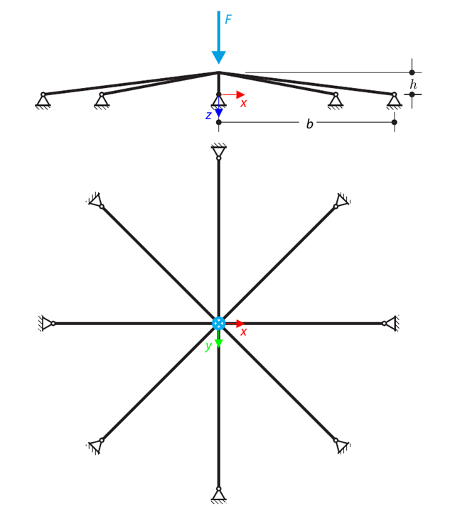
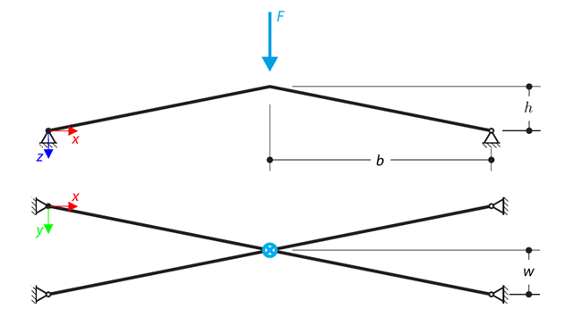
A symmetrical shallow structure is made of eight equal truss members, which are embedded into hinge supports. The structure is loaded by a concentrated force and alternatively by imposed nodal deformation over the critical limit point when the snap-through occurs. Imposed nodal deformation is used in RFEM 5 and RSTAB 8 to obtain the full equilibrium path of the snap-through. The self-weight is neglected in this example. Determine the relationship between the actual loading force and the deflection, considering large deformation analysis. Evaluate the load factor at the given deflections.
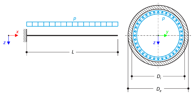
A pipe with a tubular cross-section is loaded by internal pressure. This internal pressure causes axial deformation of the pipe (the Bourdon effect). Determine the axial deformation of the pipe endpoint.
A structure is made of four truss members, which are embedded into hinge supports. The structure is loaded by a concentrated force and alternatively by imposed nodal deformation over the critical limit point, when snap-through occurs. Imposed nodal deformation is used in RFEM 5 and RSTAB 8 to obtain the full equilibrium path of the snap-through. The self-weight is neglected in this example. Determine the relationship between the actual loading force and the deflection, considering large deformation analysis. Evaluate the load factor at given deflections.
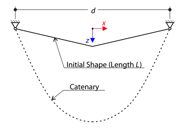
A very stiff cable is suspended between two supports. Determine the equilibrium shape of the cable (the catenary), consider the gravitational acceleration, and neglect the stiffness of the cable. Verify the position of the cable at the given test points.
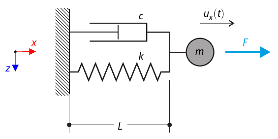
A single-mass system with dashpot is subjected to constant loading force. Determine the deflection and velocity of the dashpot endpoint in the given test time.
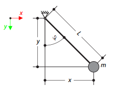
The mathematical pendulum consists of a zero‑weight rope and a mass point at its end. The pendulum is initially deflected. Determine the angle of the rope at the given test time.
A thin string is tensioned by initial strain and initially deflected. Determine the deflection of the test point at the given test times.
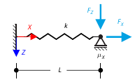
The goal of this example is to demonstrate an irreversible process caused by friction. After the loading and unloading, the end-point is in a different position than where it was at the beginning. Determine the movement of the node in the X direction.
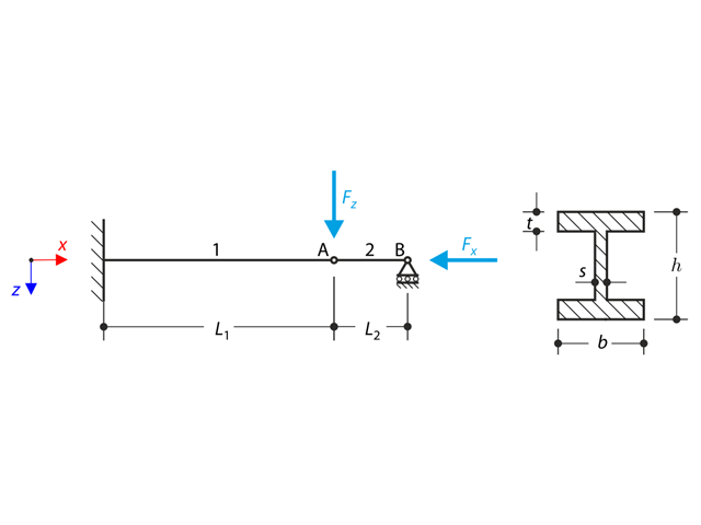
A structure made of an I-profile is fully fixed on the left end and embedded into the sliding support on the right end. The structure consists of two segments. The self-weight is neglected in this example. Determine the maximum deflection of the structure, the bending moment on the fixed end, the rotation of segment 2, and the reaction force at point B by means of the geometrically linear analysis and the second-order analysis. The verification example is based on the example introduced by Gensichen and Lumpe.
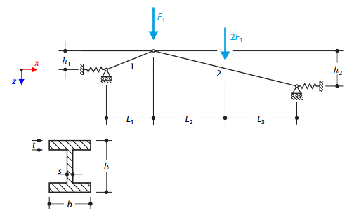
A structure made of I-profile trusses is supported on both ends by spring sliding supports and loaded by transversal forces. The self-weight is neglected in this example. Determine the deflection of the structure, the bending moment, the normal force in the given test points, and the horizontal deflection of the spring supports.
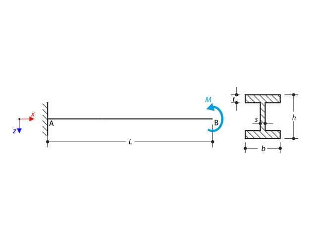
An I-profile cantilever is supported on the left end and loaded by torque. The aim of this example is to compare the fixed support with the fork support and to investigate the behavior of some representative quantities. Comparison is also made to the solution by means of plates. Small deformations are considered, and the self-weight is neglected. Determine the rotation in the midpoint of the cantilever, and in case of the member entity with warping, determine the values of the primary torsional moment, the secondary torsional moment, and the warping moment both on the left end (point A) and the right end (point B).
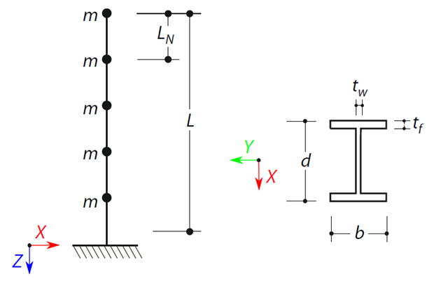
A cantilever beam with an I-beam cross-section of length L is defined. The beam has five mass points with masses m acting in the X-direction. The self-weight is neglected. The frequencies, mode shapes, and equivalent loads of this 5-DOF system are analytically calculated and compared with the results from RSTAB and RFEM.
One layered square orthotropic plate is fully fixed at its middle point and subjected to pressure. Compare the deflections of the plate corners to check the correctness of the transformation.