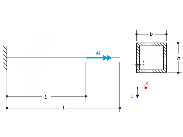
A thin-walled cantilever of a QRO-profile is fully fixed on the left end and warping is free. The cantilever is subjected to torque. Small deformations are considered, and the self-weight is neglected. Determine the maximum rotation, primary moment, secondary moment, and warping moment. The verification example is based on the example introduced by Gensichen and Lumpe.
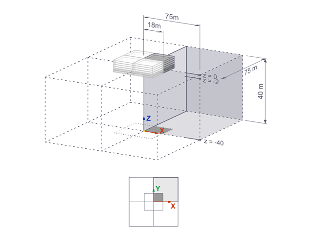
The settlements of a rigid square foundation on a lacustrine clay [1] are calculated with RFEM. One quarter of the foundation is modelled. The foundation has a width of 75.0 m in both sides. Construction stages are used to generate the results.

Consider an ASTM A992 W 18x50 beam forspan and uniform dead and live loads as shown in Figure 1. The member is limited to a maximum nominal depth of 18 inches. The live load deflection is limited to L/360. The beam is simply supported and continuously braced. Verify the available flexural strength of the selected beam, based on LRFD and ASD.
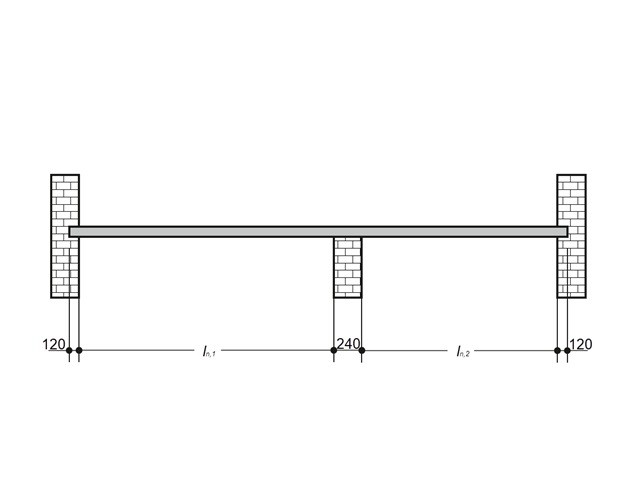
A reinforced concrete slab inside a building is to be designed as a 1.0 m stripe with members. The floor slab is uniaxially spanned and runs through two spans. The slab is fixed on masonry walls with free-rotating supports. The middle support has a width of 240 mm and the two edge supports have a width of 120 mm. The two spans are subjected to an imposed load of category C: congregation areas.
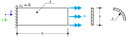
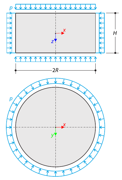
A thin plate is fixed on one side and loaded by means of distributed torque on the other side. First, the plate is modeled as a planar plate. Furthermore, the plate is modeled as one-fourth of the cylinder surface. The width of the planar model is equal to the length of one-fourth of the circumference of the curved model. The curved model thus has almost equal torsional constant to the planar model.
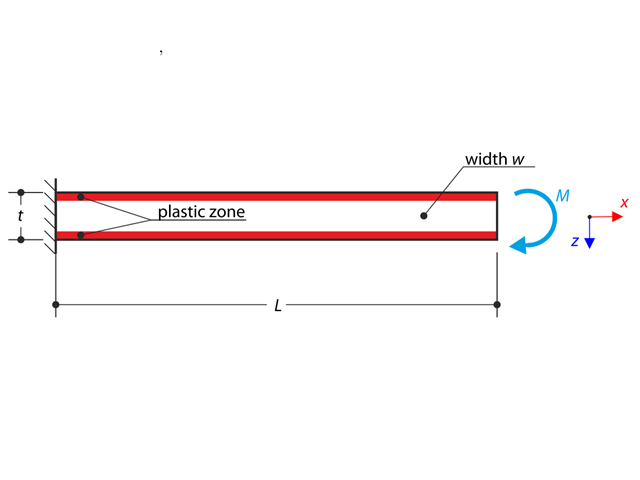
A cantilever is fully fixed on the left end and loaded by a bending moment. Plastic material is considered for the calculation.
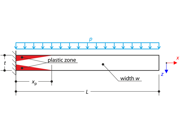
A thin plate is fully fixed on the left end and loaded by uniform pressure. Plastic material is considered for the calculation.
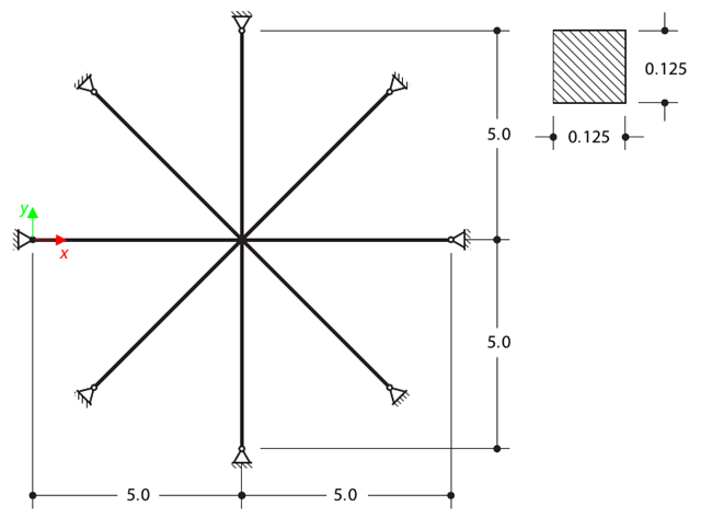
Determine the first sixteen natural frequencies of a double cross with a square cross-section. Each of the eight arms is modeled by means of four beam elements and has a pin support at the end (the x- and y-deflections are restricted). The vibrations are considered only in plane xy. The problem is defined according to The Standard NAFEMS Benchmarks.
A cylinder made of elasto-plastic soil is subjected to triaxial test conditions. Neglecting the self-weight, the goal is to determine the limit vertical stress for shear stress failure. An initial hydrostatic stress of 100 kPa is considered.
A cantilever is fully fixed on the left end and subjected to a bending moment considering plasticity.
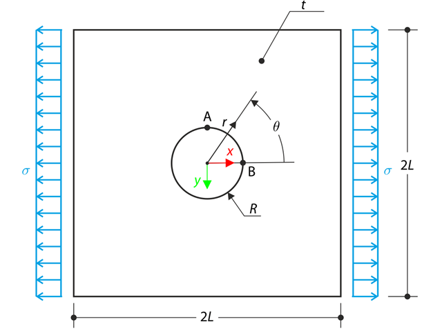
The wide plate with a hole is loaded in one direction by means of the tensile stress σ. The plate width is large with respect to the hole radius and it is very thin, considering the state of the plane stress. Determine the radial stress σr, tangential stress σθ, and shear stress τrθ around the hole.
A tapered cantilever is fully fixed on the left end and subjected to a continuous load q. Small deformations are considered and the self-weight is neglected in this example. Determine the maximum deflection.
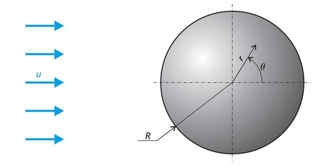
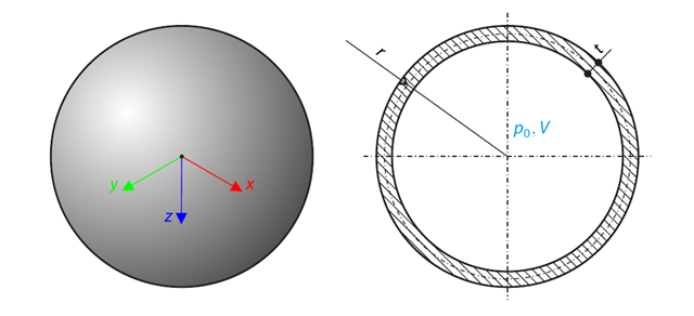
A sphere is subjected to a uniform flow of viscous fluid. The velocity of the fluid is considered at infinity. The goal is to determine the drag force. The parameters of the problem are set so that the Reynolds number is small and the radius of the sphere is also small, thus the theoretical solution can be reached - Stokes flow (G. G. Stokes 1851).
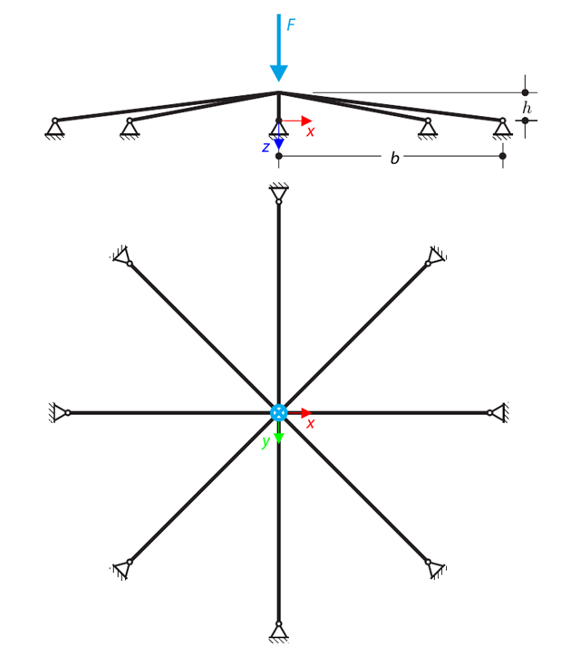
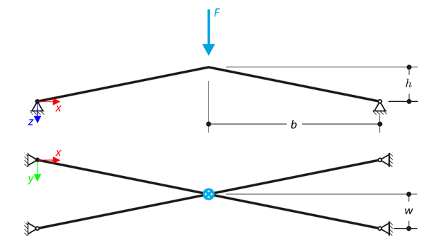
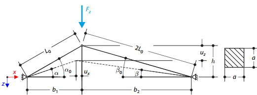
A symmetrical shallow structure is made of eight equal truss members, which are embedded into hinge supports. The structure is loaded by a concentrated force and alternatively by imposed nodal deformation over the critical limit point when the snap-through occurs. Imposed nodal deformation is used in RFEM 5 and RSTAB 8 to obtain the full equilibrium path of the snap-through. The self-weight is neglected in this example. Determine the relationship between the actual loading force and the deflection, considering large deformation analysis. Evaluate the load factor at the given deflections.
A spherical balloon membrane is filled with gas with atmospheric pressure and defined volume (these values are used for FE model definition only). Determine the overpressure inside the balloon due to the given isotropic membrane prestress. The add-on module RF-FORM-FINDING is used for this purpose. Elastic deformations are neglected both in RF-FORM-FINDING and in the analytical solution; self-weight is also neglected in this example.
A structure is made of four truss members, which are embedded into hinge supports. The structure is loaded by a concentrated force and alternatively by imposed nodal deformation over the critical limit point, when snap-through occurs. Imposed nodal deformation is used in RFEM 5 and RSTAB 8 to obtain the full equilibrium path of the snap-through. The self-weight is neglected in this example. Determine the relationship between the actual loading force and the deflection, considering large deformation analysis. Evaluate the load factor at given deflections.
Consider an ASTM A992 W 18×50 beam forspan and uniform dead and live loads as shown in Figure 1. The member is limited to a maximum nominal depth of 18 inches. The live load deflection is limited to L/360. The beam is simply supported and continuously braced. Verify the available flexural strength of the selected beam, based on LRFD and ASD.
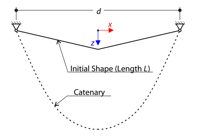
A very stiff cable is suspended between two supports. Determine the equilibrium shape of the cable (the catenary), consider the gravitational acceleration, and neglect the stiffness of the cable. Verify the position of the cable at the given test points.
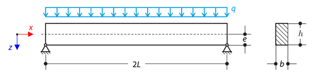
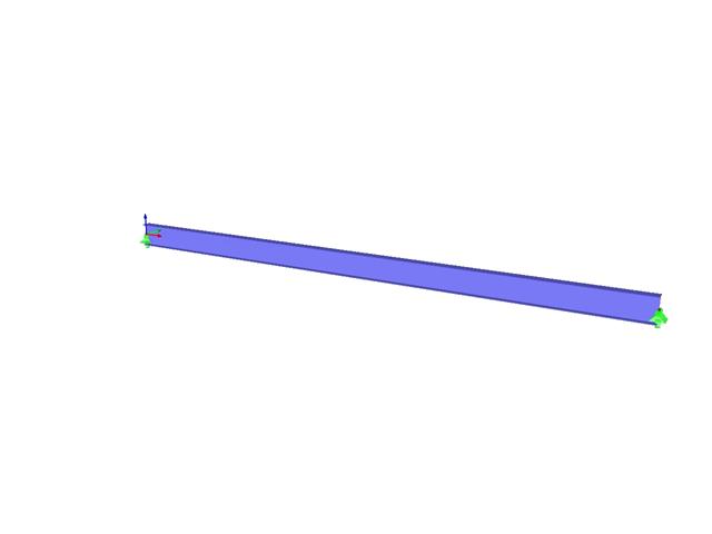
A pinned beam with a rectangular cross‑section is subjected to distributed loading and shifted vertically by eccentricity. Considering the small deformation theory, neglecting the self‑weight, and assuming that the beam is made of isotropic elastic material, determine the maximum deflection.
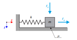
A simple oscillator consists of mass m (considered only in the x-direction) and linear spring of stiffness k. The mass is embedded on a surface with Coulomb friction and is loaded by constant-in-time axial and transverse forces.
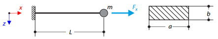
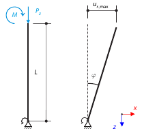
A cantilever of rectangular cross‑section has a mass at the end. Furthermore, it is loaded by an axial force. Calculate the natural frequency of the structure. Neglect the self‑weight of the cantilever and consider the influence of the axial force for the stiffness modification.
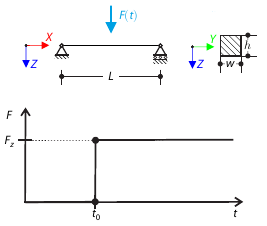
A concentrated force is suddenly applied at the mid‑span of a simply supported beam at a given time. Considering only the small deformation theory, determine the maximum deflection of the beam.
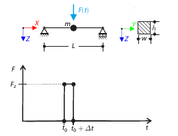
A concentrated force is applied for a short period of time at the mid‑span of a simply supported beam. Considering only the small deformation theory and assuming that the mass of the beam is concentrated at its mid‑span, determine its maximum deflection.
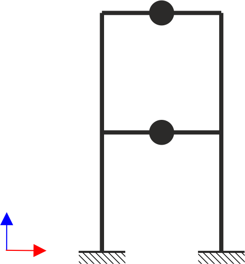
A two‑story, single‑bay frame structure is subjected to earthquake loading. The modulus of elasticity and cross‑section of the frame beams are much larger than those of the columns, so the beams can be considered rigid. The elastic response spectrum is given by the standard SIA 261/1:2003. Neglecting self-weight and assuming the lumped masses are at the floor levels, determine the natural frequencies of the structure. For each frequency obtained, specify the standardized displacements of the floors as well as equivalent forces generated using the elastic response spectrum according to the standard SIA 261/1.2003.
A structure is made of two trusses of unequal length, which are embedded into the hinge supports. The structure is loaded by concentrated force. The self-weight is neglected. Determine the relationship between the loading force and the deflection, considering large deformations.
A thin-walled cantilever of a QRO-profile is fully fixed on the left end and warping is enabled. The cantilever is subjected to torque. Small deformations are considered, and the self-weight is neglected. Determine the maximum rotation, primary moment, secondary moment, and warping moment. The verification example is based on the example introduced by Gensichen and Lumpe.
Consider a rigid scaffolding tube, fixed at the bottom using the Scaffolding Nodal Support and loaded by both a moment and a force. Calculate the maximum deflection with consideration of initial slippage.
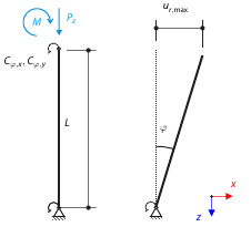
Consider a rigid scaffolding tube, fixed at the bottom using the Scaffolding Nodal Support and loaded by both a moment and a force. Calculate the maximum radial deflection by exceeding the capacity of the scaffolding support.
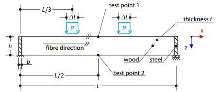
A timber beam reinforced by two steel plates at the ends is loaded by pressure. The wood fibers are parallel to the upper loaded side of the beam. The plastic surface is described according to the Tsai-Wu plasticity theory.
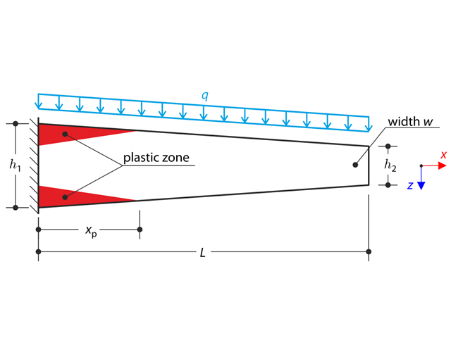
A tapered cantilever is fully fixed on the left end and loaded by a continuous load. Plastic material is considered for the calculation.