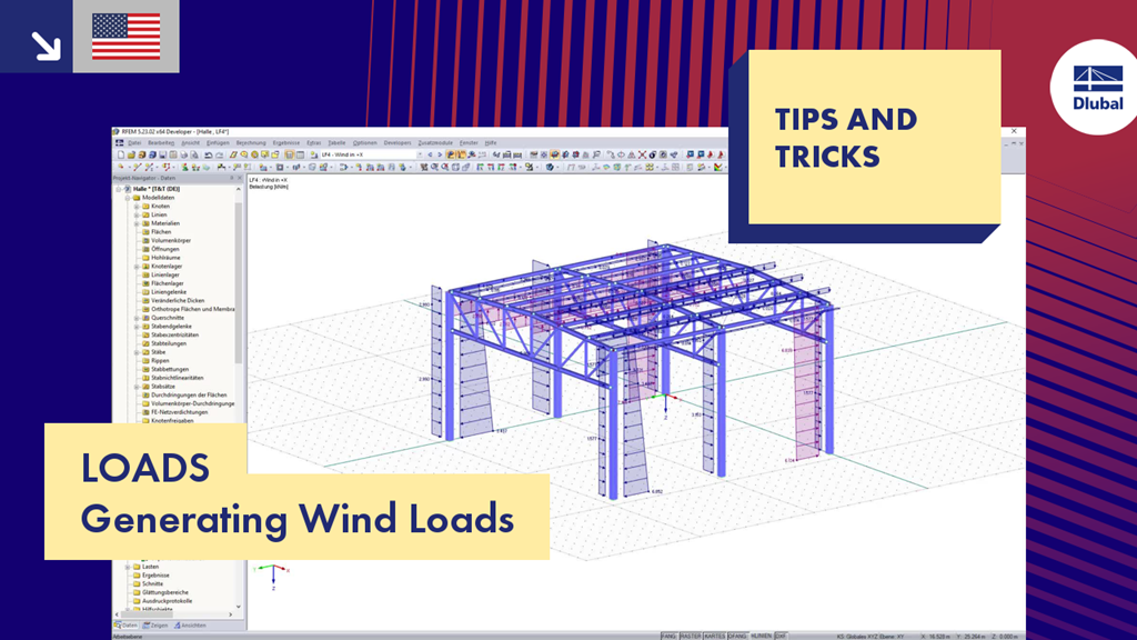
The video shows the automatic generation of wind loads using the load generator in RFEM. As an example, the wind load is determined for a three-dimensional steel hall according to Eurocode.
T&T 006 | Loads - Generating Wind Loads
Links
Do you have any questions?
In Germany, DIN EN 1991-1-4 with the National Annex DIN EN 1991-1-4/NA regulates the wind loads. The standard applies to civil engineering works up to an altitude of 300 m.
If the wind load for buildings or structures is to be determined by the simultaneous assumption of aerodynamic pressure and suction coefficients on the windward and leeward sides of the building, the correlation of the wind pressure on zones D and E of the wall surfaces may be taken into account.
RFEM and RSTAB allow you easily to consider wind load effects on a three-dimensional building according to ASCE/SEI 7‑16. This article explains the complex theory of entering wind loads in the software. You can find the wind load under "Tools" → "Generate Loads" → "From Wind Loads".
In RFEM 5 as well as RSTAB 8 in RF-/FOUNDATION Pro, you can save the foundation dimensions for all five foundation types as foundation templates in a user-defined database and use them later in other models.
Wind loads can be automatically generated as member loads on the following structural components (optional with internal pressure for open buildings):
- Vertical walls
- Flat roofs
- Monopitch roofs
- Duopitch/troughed roofs
- Vertical walls with roof
The following standards are available:
- EN 1991-1-3 (incl. National Annexes)
- DIN 1055-4
- CTE DB-SE-AE
- ASCE/SEI 7-16
There are load generators available for beam structures, creating snow loads according to ASCE/SEI 7-10. The load cases are generated depending on the roof shape. Another generator creates coating loads (ice). You can save recurring load combinations as templates.
In the "Edit Section" dialog box, you can display the buckling shapes of the Finite Strip Method (FSM) as a 3D graphic.
- Design of five types of seismic force-resisting systems (SFRS) includes Special Moment Frame (SMF), Intermediate Moment Frame (IMF), Ordinary Moment Frame (OMF), Ordinary Concentrically Braced Frame (OCBF), and Special Concentrically Braced Frame (SCBF)
- Ductility check of the width-to thickness ratios for webs and flanges
- Calculation of the required strength and stiffness for stability bracing of beams
- Calculation of the maximum spacing for stability bracing of beams
- Calculation of the required strength at hinge locations for stability bracing of beams
- Calculation of the column required strength with the option to neglect all bending moments, shear, and torsion for overstrength limit state
- Design check of column and brace slenderness ratios
Recommended Products for You