Answer:
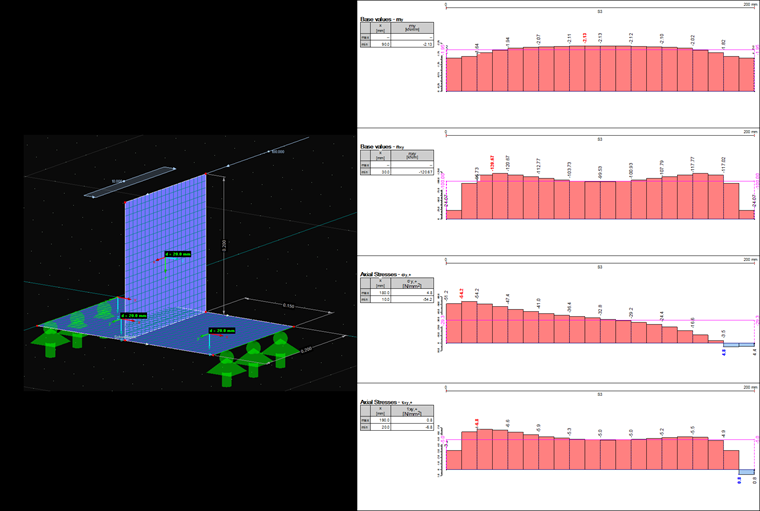
In order to obtain the weld stresses, it is important to know which type of surface stresses resulting in RFEM are relevant. The image shows a simple example: a lap joint fixed in the z-direction is subjected to a distributed load of 100 kN/m at the upper end in the x-direction and to a distributed load of 10 kN/m in the y-direction.
To determine the correct stresses, you have to know the local coordinate system of the surface. It can be activated in the Display navigator under "Model → Surfaces → Surface Axis Systems x, y, z". All stresses with "+" in the index represent the stress on the upper side; that is, the side of the positive local z-axis. When displaying the surface moments, it is necessary to pay attention to the fundamental difference between the surface and member internal forces: while the member moment My "rotates" about the local member axis y, the surface moment my acts in the direction of the local surface axis y; that is, about the axis x of this surface.
In this particular case, this means: my represents the bending moment of the flap joint in the direction of the global y-axis. Therefore, the resulting value must be 2 kNm/m. The average in the diagram shown in the figure confirms this with the value of 1.95 kNm/m (deviations can be reduced by a finer FE mesh). The average of the shear flow is 100 kN/m and thus corresponds to the applied load.
Therefore, the stress σy,+ reflects the compressive stress of the lap joint on the upper side of the surface; τxy,x corresponds to the shear stress in the interface on the same side.
The stresses should only be evaluated if the weld thickness is equal to the surface thickness. Otherwise, you should determine the stresses manually from the applied internal forces.