When I create a user-defined result value, the RFEM solver window opens briefly and the calculation is apparently performed again. Why? I have already performed the calculation before.
Answer
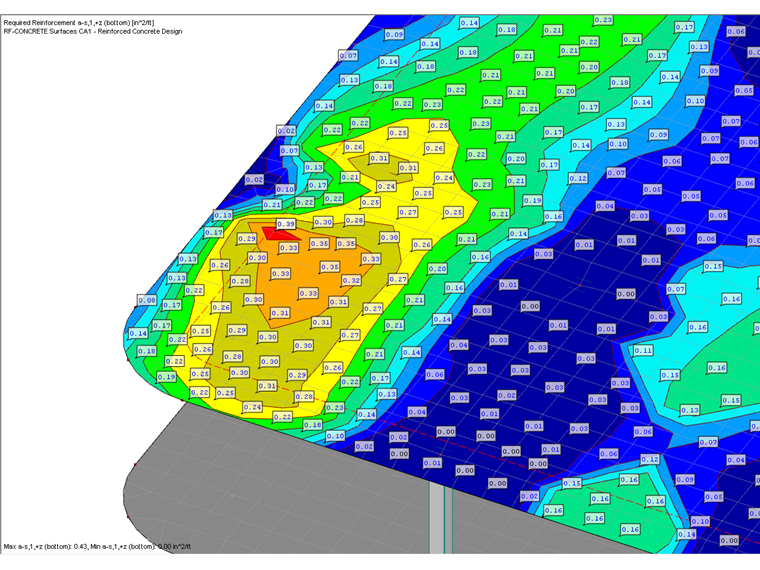
If you have performed a calculation in RF‑CONCRETE Surfaces, the results are available on FE mesh nodes and on grid points.
If you set a user-defined result value in a surface, an interpolated value from the existing values from the calculation in RF‑CONCRETE Surfaces is displayed on the FE mesh nodes first. This interpolated value is displayed while the user-defined result value is being set (when moving the mouse pointer over the surface).
If closing the command to set the user-defined result value (ESC key), RF‑CONCRETE Surfaces recalculates this actual value at this location. As a consequence, the solver window is displayed briefly. Depending on the complexity of the calculation, this solver window is only displayed for a short time or several seconds.
Due to the initial display of the interpolated values and the subsequent calculation of the actual result value, there may be small differences.
Keywords
User-defined Result value Grid FE mesh node FE mesh point Solver Solver window
Downloads
Contact us
Did you find your question?
If not, contact us via our free e-mail, chat, or forum support, or send us your question via the online form.
Recommended Events
Eurocode 5 | Timber structures according to EN 1995-1-1
Online Training 17 March 2021 8:30 AM - 12:30 PM CET
Eurocode 3 | Steel structures according to DIN EN 1993-1-1
Online Training 18 March 2021 8:30 AM - 12:30 PM CET
Eurocode 3 | Steel structures according to DIN EN 1993-1-1
Online Training 6 May 2021 8:30 AM - 12:30 PM
Eurocode 2 | Concrete structures according to DIN EN 1992-1-1
Online Training 11 May 2021 8:30 AM - 12:30 PM
Eurocode 5 | Timber structures according to DIN EN 1995-1-1
Online Training 20 May 2021 8:30 AM - 12:30 PM
RFEM | Structural dynamics and earthquake design according to EC 8
Online Training 2 June 2021 8:30 AM - 12:30 PM
Stability Design in Steel Construction with RFEM and RSTAB
Webinar 1 December 2020 2:00 PM - 2:45 PM CET
Videos
KB000610 | Automatically Dimensioning the Foundation Slab Geometry with RF-/FOUNDATION Pro
Length 0:40 min
KB 000674 | Defining Mandrel Diameter for Foundation Reinforcement in RF-/FOUNDATION Pro
Length 0:36 min
KB 000605 | Setting the Concrete Cover in RF-/FOUNDATION Pro According to EN 1992-1-1
Length 0:32 min
KB 000655 | Longitudinal reinforcement to be applied for the shear force design according to EN 1...
Length 0:34 min
Models to Download
Knowledge Base Articles

New
Using Modified Stiffnesses for Dynamic Calculations
In RFEM, it is possible to modify stiffnesses for materials, cross -sections, members, load cases, and load combinations in many places.
Screenshots
Product Features Articles

Material Model Orthotropic Masonry 2D
The material model Orthotropic Masonry 2D is an elastoplastic model that additionally allows softening of the material, which can be different in the local x- and y-direction of a surface. The material model is suitable for (unreinforced) masonry walls with in-plane loads.
Frequently Asked Questions (FAQ)
- How are the signs for the release results of a line release and line hinges interpreted?
- How can I create a curved or arched section?
- Is it possible to manually specify a longitudinal reinforcement for design in RF‑PUNCH Pro?
- Can I simulate the cracked state of a concrete cross-section for a bending beam with the "Isotropic Nonlinear Elastic 1D" material model?
- Why is the deflection of the reinforced concrete floor sometimes greater when selecting a larger basic reinforcement?
- I have a question about the message No. 47 in RFEM. What is the exact meaning of the word "integrate"? What is the resulting effect?
- How can I view the depth of the concrete compression zone in RF‑/CONCRETE?
-
If I do not specify any basic reinforcement in RF‑CONCRETE Surfaces, I obtain the value X as an additionally required reinforcement. If I enter this value X as the provided basic reinforcement, I correctly do not get any additional required reinforcement.
However, if I enter a lower value than the determined required total reinforcement as the basic reinforcement, the additionally required reinforcement is increased in such a way that the originally required reinforcement content is exceeded. Why? - Why does the RF‑CONCRETE Surfaces add-on module not increase the amount of reinforcement until the SLS designs have a design ratio of 1.0?
- How can I get the member end forces to design the connections?
Customer Projects
Associated Products