Answer:
These increments result from the creep components in a quasi-permanent combination. You can find the overview of which combinations are to be analyzed in the serviceability limit state according to DIN EN 1995-1-1 or in the links of the FAQ:
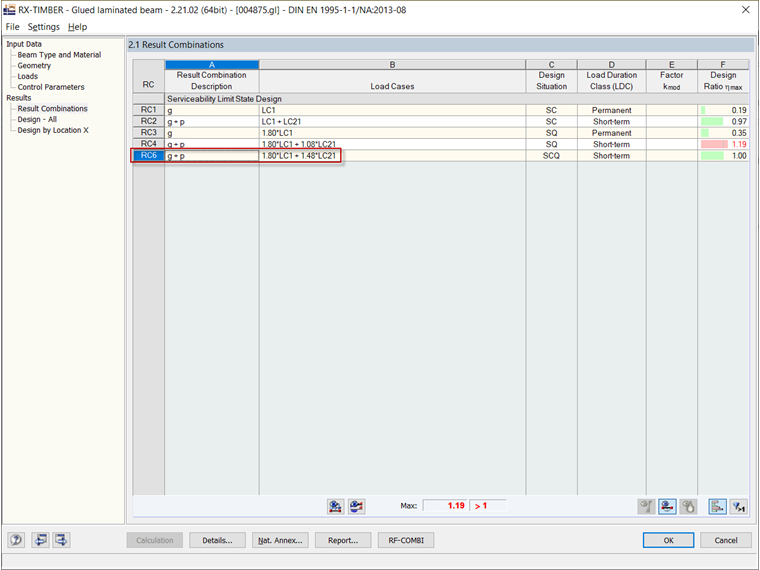
The creep components are then simply added to the characteristic deformation; for example, with 0.8 × self-weight. This results in the factor of 1.8 (see also Section 2.2.3 in EN 1995‑1‑1).
In this specific case, the following coefficients must be applied for the quasi-permanent design situation:
Gk ⋅ (1 + 0.8) + Qk ⋅ (1 + 0.6 ⋅ 0.8) = Gk ⋅ 1.8 + Qk ⋅ 1.48