The structural analysis software RFEM 6 is the basis of a modular software system. The main program RFEM 6 is used to define structures, materials, and loads of planar and spatial structural systems consisting of plates, walls, shells, and members. The program also allows you to create combined structures as well as to model solid and contact elements.
RSTAB 9 is a powerful analysis and design software for 3D beam, frame, or truss structure calculations, reflecting the current state of the art and helping structural engineers meet requirements in modern civil engineering.
Do you often spend too long calculating cross-sections? Dlubal Software and the RSECTION stand-alone program facilitate your work by determining section properties of various cross-sections and performing a subsequent stress analysis.
Do you always know where the wind is blowing from? From the direction of innovation, of course! With RWIND 2, you have a program at your side that uses a digital wind tunnel for the numerical simulation of wind flows. The program simulates these flows around any building geometry and determines the wind loads on the surfaces.
Are you looking for an overview of snow load zones, wind zones, and seismic zones? Then you are in the right place. Use the Geo-Zone Tool to determine quickly and efficiently snow loads, wind speeds, and seismic data according to ASCE 7‑16 and other international standards.
Would you like to try out the capabilities of the Dlubal Software programs? You have the opportunity to do so! The free 90-day full version allows you to thoroughly test all our programs.
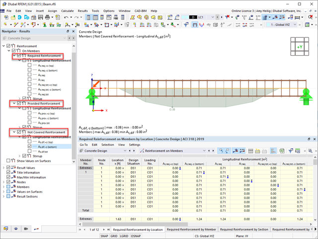
In the current state of RFEM 6, the user must manually define the shear and longitudinal reinforcement for members. This is considered the "Provided Reinforcement" within the Concrete Design add-on. The add-on calculation will then determine the "Required Reinforcement" needed from the analysis and further output the "Not Covered Reinforcement". The user must manually apply additional reinforcement if the "Required Reinforcement" is not met.
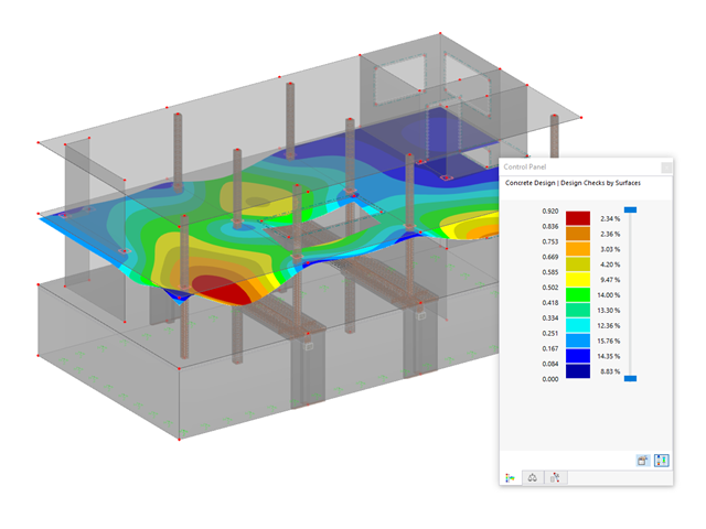
For surfaces RFEM 6 can design automatically the reinforcement.
Design of Surface Reinforcement
It is planned for the future to have an automatic design also of the member reinforcement rather than only the manual input option.
Yes, the deformation analysis taking into account the cracked state in the cross-section is included in the concrete design in RFEM 6.
For this, the effective stiffness is calculated for each element in the concrete design according to the existing cross-section state of cracked (state II) or uncracked (state I), and then used in a second FEM calculation for the deformation.
In RFEM 5, this corresponds to the solution in the "RF‑CONCRETE Deflect" add-on module. In RFEM 6, this method is included in the concrete design.
Further information about determining the crack state as part of the deformation analysis can be found in the technical article at the following link.
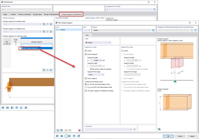
All members when using the Design Add-ons for serviceability checks are considered supported at the end nodes by default. If the member is instead a cantilever or includes an internal support for a combination of both a cantilever and supported at both ends member type, a new Design Support should be defined under the member details.
The Design Support option can be found under the member dialog box under Design Supports & Deflection tab. Supports can be added to any nodes detected along the member length such as the member start, member end, or internal nodes.
Under the New Design Support dialog box, you can set the type of support from the drop-down including general, concrete, or timber. The "general" will give the program guidance on the deflection member type and which limiting deflection ratio to reference from the Serviceability Configurations whether cantilever (e.g., L/180) or supported on both ends (e.g., L/360). The alternative types "concrete" and "timber" will also influence the deflection design, but have additional strength design options incorporated such as moment and shear internal force modification for concrete design and a stress perpendicular to grain check for timber design.
For additional detailed information on this new setting in RFEM 6 including a "timber" type design support, refer to the webinar listed below under Links at time 51:05.
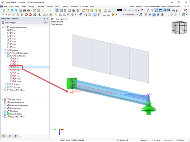
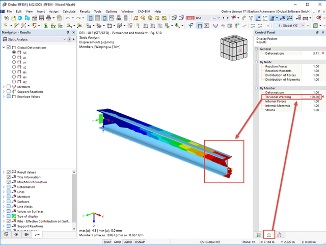
Both support forces and loads are assumed for the calculation with warping torsion in the centroid. Accordingly, an asymmetric cross-section would automatically receive torsion; see the image.
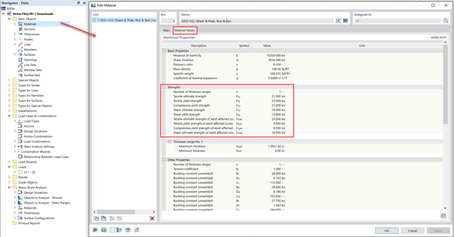
Some materials have multiple limit stress limits for compression, tension, and so on. For these materials, the limiting stress must be input manually by the user.
The limit stress values are listed under the Material Values tab.
These values can be added in the Member/Surface Configurations under the User limit stress type.
The punching results can also be found in the Results navigator.The results are divided into the design checks "On Nodes" and the reinforcement "On Nodes".The punching loads as well as the distribution of the shear forces at the critical perimeter (smoothed and unsmoothed) are the intermediate results of the design checks and are arranged accordingly in this part of the navigator.
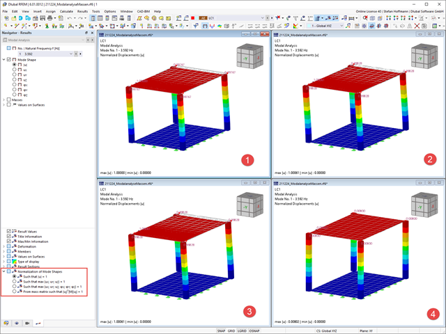
The warping of a cross-section can be displayed in the "full mode". For this, it is reasonable to increase the display factor for torsional warping in the control panel; see Image 01.
Furthermore, you can select the value of the local deformation ω [1/m] in the Results navigator; see Image 02.
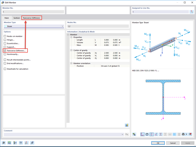
After activating Torsional Warping in the Base Data, you can define warping springs and warping restraints. For this, select the Transverse Stiffeners option in the "Edit Member" dialog box; see Image 01.
In the "Transverse Stiffener" tab, you can create several transverse member stiffeners and define the necessary parameters using the "New Transverse Member Stiffener" button. For the "End plate" stiffener type, the resulting warp spring is determined automatically; see Image 02.
In addition to other variants, you can also define a rigid warping restraint or user-defined warping spring stiffness under the "Warping restraint" stiffness type.
As an alternative, you can create member transverse stiffeners using the Data navigator or the menu bar "Insert", "Types for Members", "Member Transverse Stiffeners". In this case, you can use the select function in the "New Member Transverse Stiffness" dialog box to assign them to the corresponding members.
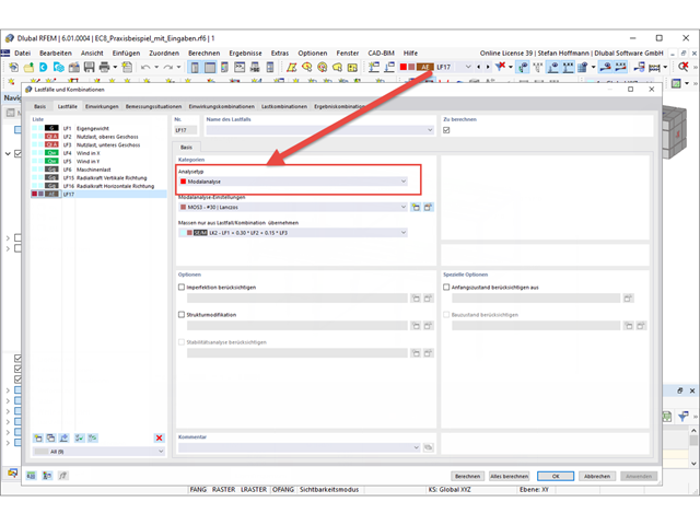
You can also define structural modifications in a load case of the Modal Analysis type. Thus, you can access the stiffness modifications of the individual objects and deactivate the selected objects, if necessary.
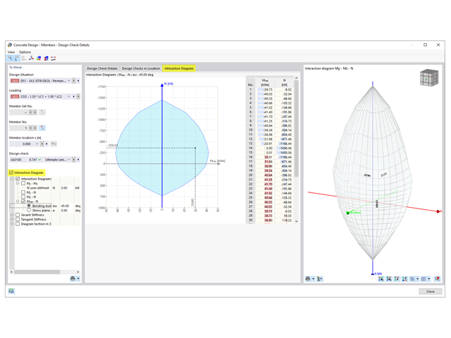
To display the interaction diagram, open the "Design Details" dialog box of Concrete Design.
On the left side of the dialog box, you can then select the "Interaction Diagram". Thus, an additional tab called "Interaction Diagram" appears. You can control the settings for the result display here.
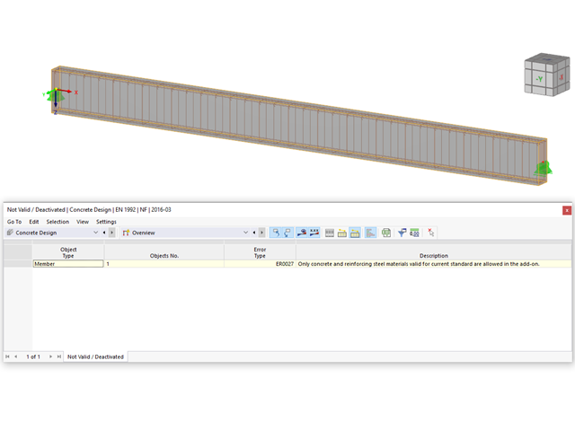
Check to see if the material assigned to the members is compatible with the standard selected for the design in the "Concrete Design" add-on.
Furthermore, please check to see if all design properties (durability class, concrete cover, shear and longitudinal reinforcement, and so on) have been specified correctly in the "Edit Member" dialog box.
In order to display the mode shapes of your dynamic analysis, you have to create a load case of the Modal Analysis type and specify your settings for the modal analysis there.
After the calculation, you can evaluate your results in the Results navigator. You can see further information in the table.
You can adjust the display of the mode shape normalization directly in the Results navigator. If the setting is changed, no recalculation is necessary.
Depending on the setting, the largest displacement or deformation represents the reference value 1, to which the other results are scaled.
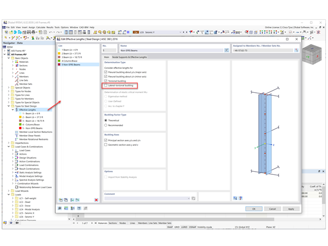
In the Effective Length dialog box, you can simply uncheck the "Lateral Torsional Buckling" option to exclude this check in the design add-on.
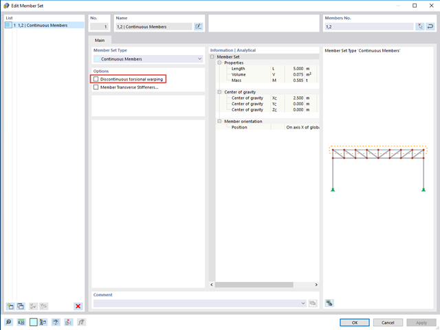
Releases for warping are at each member end by default. Splitting members leads to a warping release.
If you do not want to have a warping release there, but rather continuous warping, you need to define a member set. When activating the "Torsional Warping" add-on, the warping is transferred automatically. If this is not desired for the member set, select the "Discontinuous torsional warping" option; see the image.
No, this is not possible in the current state of development of RFEM 6.
See also the FAQ for RFEM 5 and RF‑CONCRETE Surfaces by clicking the link below.The design concept is currently structured similarly and is based on the reinforcement on the top and bottom sides.
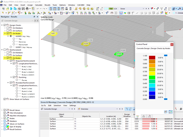
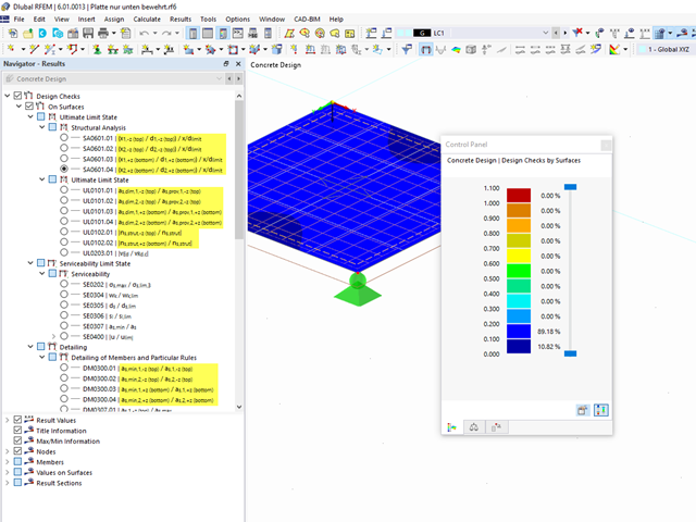
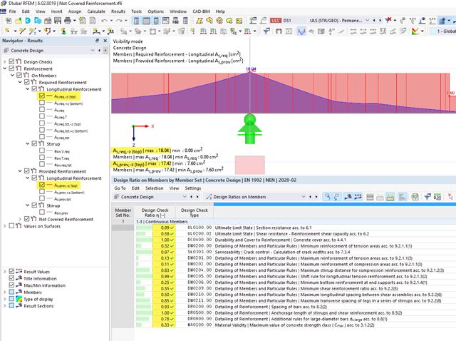
It can happen that all design checks are fulfilled for a particular member or set of members, but a "Not Covered Reinforcement" result is still output. See also Image 01 and Image 02.
The reason for this is that the distribution of the "Provided Reinforcement" on the upper and lower positions is generated from the rebar arrangement within the cross-section.
The rebars above the center of gravity are assigned to the "upper position" and the rebars below the center of gravity are assigned to the "lower position". This means that the distribution of the "Provided Reinforcement" does not consider the actual distribution of the zero line within the cross-section, and checks which rebar is actually in the tension zone.
However, the actual distribution of the zero line within the cross-section is checked during the design. Thus, the rebars that have been geometrically assigned to the "lower reinforcement" (the provided reinforcement distribution) can be mathematically assigned to the tension reinforcement. This can be seen in Image 03. The rebars marked in red have been assigned geometrically to the lower reinforcement. However, the stress distribution within the cross-section shows that they are also subjected to tension and apply to the design checks accordingly. In the design, all members (marked in red and green in Image 03) are applied. Therefore, all the design checks are fulfilled at this location, although the distribution of the "Not Covered Reinforcement" suggests otherwise.
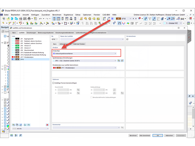
To perform an earthquake analysis, you need a modal analysis and then a load case of the Response Spectrum Analysis type.
After you have performed your modal analysis, create a new load case. Here you will find the usual settings from the previous program generation.
In the Response Spectrum tab, you can define your response spectrum as usual. If you want to use a response spectrum according to the standard, make sure that the desired standard is selected in the general data of Standards II.
In the Selection of Modes tab, you can select the mode shapes and filter them, if necessary.
After the load case has been calculated, you obtain the results.
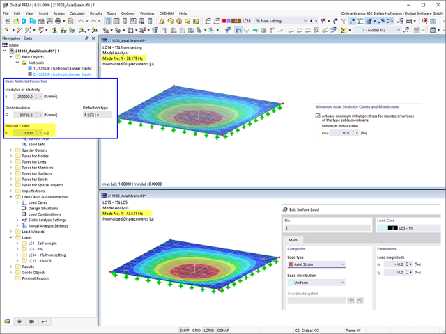
In the modal analysis settings, you can set the minimum axial strain for cables and membranes in order to apply an initial prestress to the objects and thus improve the convergence of the calculation. The initial prestress is applied to the objects in a simplified approach.
If you compare this setting with a surface load of the Axial Strain load type, you should pay attention to the fact that the two approaches differ. With the surface load, you perform a calculation in such a way that the actual prestress can deviate from the specified prestress. The calculation also takes into account other boundary conditions, such as the Poisson's ratio of the material.
You can easily check this if you vary the Poisson's ratio of the material. A Poisson's ratio other than 0 causes the deformation to interact in the x- and y-directions of the surface, which no longer results in a constant stress/strain over the entire surface.
If the Poisson's ratio is 0, you obtain the same results.
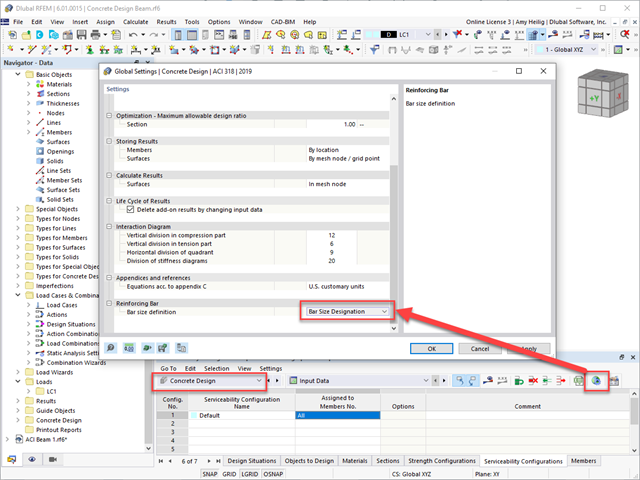
Under the RFEM 6 Concrete Design add-on - Global Settings - Reinforcing Bar - Bar size definition, the default setting "Bar Size Designation" can be changed to "Nominal Diameter". This option will allow the user to set the bar size diameter directly rather than selecting a default bar size from the drop-down.