61 Results
View results:
Sort by:
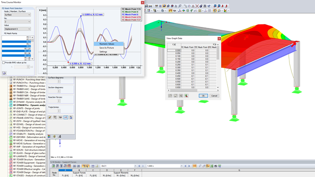
Question
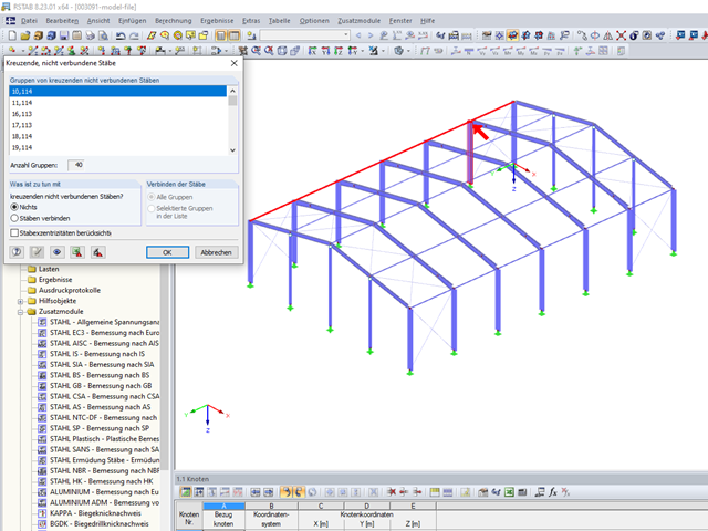
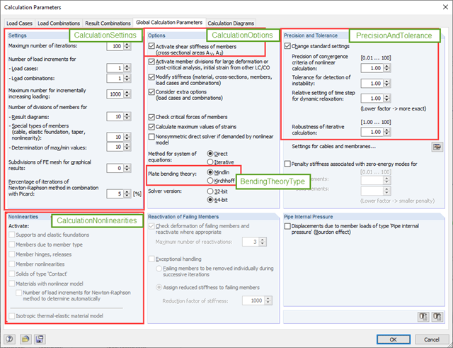
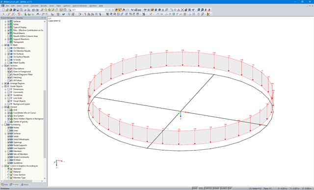
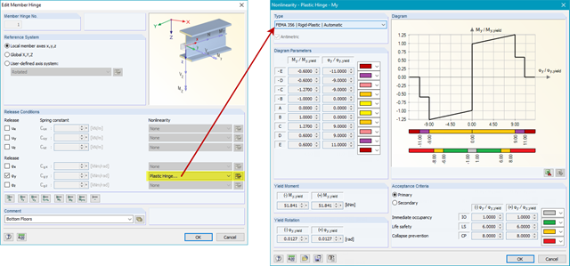
Which tools are available for a pushover analysis?
Question
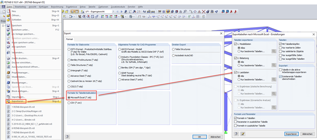
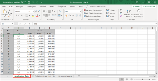
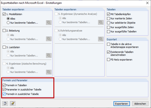
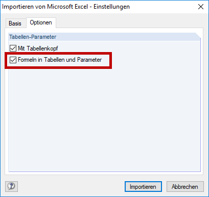
When importing model data from Excel, only values are transferred instead of formulas. What can I do?

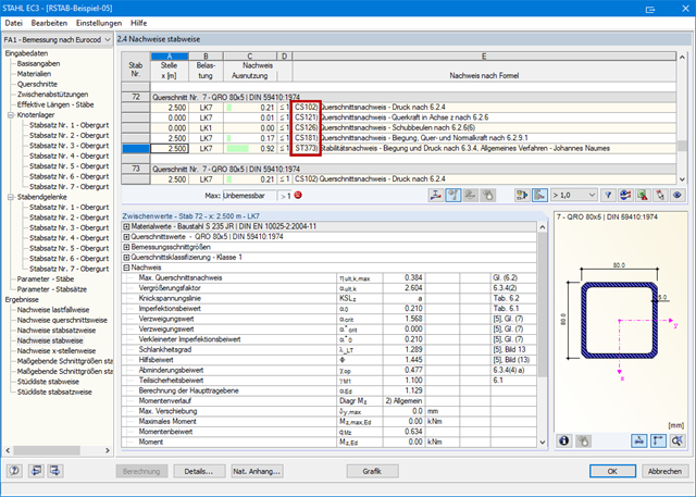
Question
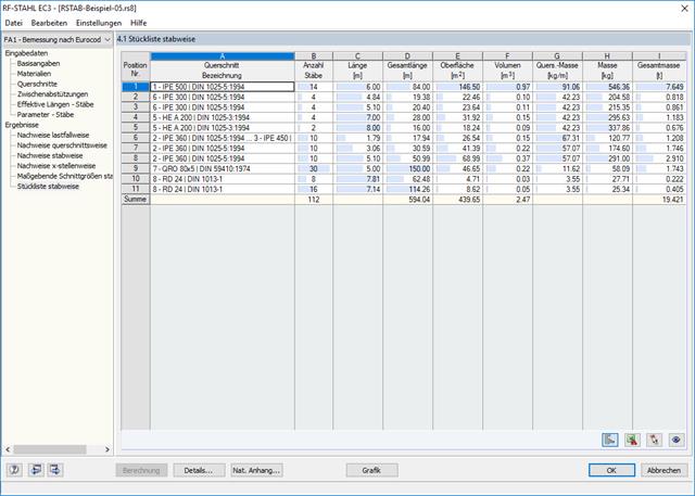
How can I retrieve the results of the STEEL EC3 add-on module, related to a load case or a cross-section, via RS‑COM?