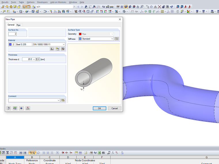
This option allows you to define and create at the relevant line a surface of the "pipe" type by means of the material, the thickness of the surface, and the radius.
Mr. Lex is responsible for developing products for glass structures and for quality assurance of the RFEM program. He also provides technical support for our customers.
After activating the RF‑PIPING add‑on module, a new toolbar is available in RFEM and the project navigator and tables are extended. The piping system is now modeled in the same way as the members. Pipe bends are defined simultaneously by tangents (straight pipe sections) and radius. Thus, it is easy to subsequently change bend parameters.
It is also possible to extend the piping subsequently by defining special components (expansion joints, valves, and others). The implemented libraries of structural components facilitate the definition.
Continuous pipe sections are defined as sets of piping systems.
For piping loads, member loads are assigned to the respective load cases. The combination of loads is included in piping load combinations and result combinations.
After the calculation, you can display deformations, member internal forces, and support forces graphically or in tables.
Pipe stress analysis according to standards can then be performed in the RF‑PIPING Design add‑on module. You only need to select the relevant sets of piping systems and load situations.
After modeling piping systems in RFEM using RF‑PIPING and defining loads as well as load and result combinations, you can carry out pipe stress analysis in the RF‑PIPING Design add‑on module.
You can select all or only some pipelines and loads, load or result combinations for piping design. The material library provides various materials according to EN 13480‑3, ASME B31.1‑2012, and ASME B31.3‑2012 standards.
After the calculation, the results are displayed in clearly arranged windows; for example, by cross‑section, by pipeline, or by members. You can also display the design ratio graphically on the entire model in RFEM. This way, you can quickly recognize critical or oversized areas of the cross-section.
In addition to the input and result data, including design details displayed in tables, you can add all graphics into the printout report. This way, comprehensible and clearly arranged documentation is guaranteed. You can select the report contents and extent specifically for the individual designs.