Separate Load Entry for Structure or Foundation Design
Technical Article
In RF-/FOUNDATION Pro, the foundation design requires the definition of corresponding loading (load cases, load combinations, or result combinations) for different design situations (STR, GEO, UPL, or EQU).
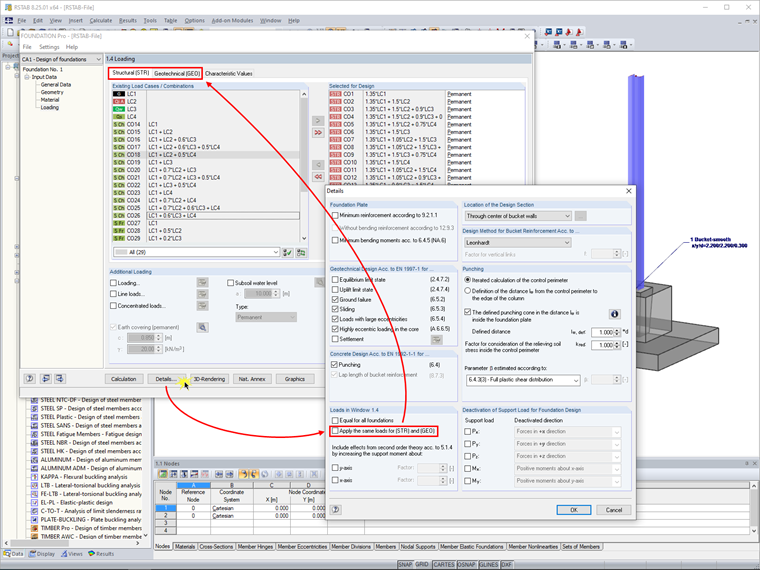
By default, the loads for designs are entered for the design situations (STR) and (GEO) in Window 1.4 Loading. This means that the same loads are used for these designs.
In RF-/FOUNDATION Pro, you can also change this setting, if necessary. To do this, clear the "Apply the same loads for (STR) and (GEO)" check box in the "Details" dialog box. Thus, you adjust Window 1.4 Loading, so you can enter the loading separately for the designs of the structure and the foundation.
Author

Dipl.-Ing. (FH) Paul Kieloch
Product Engineering & Customer Support
Mr. Kieloch provides technical support to our customers and is responsible for the development in the area of reinforced concrete structures.
Keywords
Foundation Approach 2 Ground failure Bending design Geotechnics STR GEO
Links
Write Comment...
Write Comment...
Contact Us
Do you have any further questions or need advice? Contact us via phone, email, chat or forum or find suggested solutions and useful tips on our FAQ page, available 24/7.

Database of Foundation Templates
In RFEM 5 as well as RSTAB 8 in RF-/FOUNDATION Pro, you can save the foundation dimensions for all five foundation types as foundation templates in a user-defined database and use them later in other models.

New
Application of Connections to the Structure | Steel Joints
- The proposed connection can be applied to all selected nodes in the structure
- The location of the connection can be defined using the "Main" tab of the Add-on dialog box
- The design is performed for all connections in the structure and after the calculation, the results on all connections can be displayed
- The table shows the results for the individual connections, each connection is designed and can be saved separately
-
How do I set a release for warping?
- How can I define a warping spring or a warping restraint?
- At which point on a cross-section are the supports and loads assumed for the calculation with warping torsion?
- The limit stress is activated, but my stress ratio is “non-designable” in the Stress-Strain Analysis add-on. What could be the reason?
- How can I deactivate the 7th degree of freedom for certain members or cross-sections only?
- How can I define a warping spring or a warping restraint?