


Background
The calculation of internal forces is performed by considering the elastic material behavior. One wall surface transfers its bending by the nonlinear distribution of the axial force. This distribution can vary, depending on the ratio of height (h) to length (l).
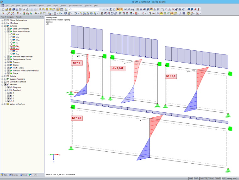
The smaller is the h/l ratio, the more the distribution approaches to the straight line. If you perform the surface design using these internal forces, the result is a distribution of the required longitudinal reinforcement that corresponds to a wedge.
However, this reinforcement arrangement is not correct because the concrete design is based on a cracked state. The strain of the reinforcement at the bottom edge may have been long exceeded while the upper reinforcement layers are not affected.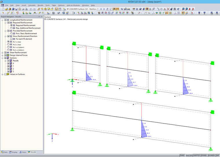
Generally, there are two options for the design in RFEM:
1. Evaluation Based on Sections
2. Design Using Result Member
Evaluation Based on Sections
This option should always be applied if the h/l ratio > 0.5. After calculating the required reinforcement in the RF-CONCRETE Surfaces add-on module, a vertical section is applied to the governing locations.
When evaluating the shear reinforcement, the maximum value of the vertical reinforcement is used (for example, from as,2,-z and as,2,+z), and is undiminished until the beam top edge is created on both sides.
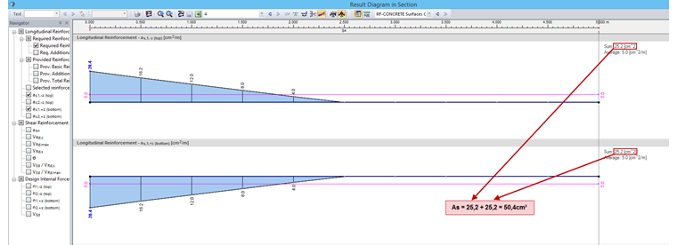
For the bending reinforcement, you can activate the result interpretation option in the detailed settings of the section dialog box. It is necessary to make sums from both horizontal reinforcements; for example, as,1,-z and as,1,+z. The determined total longitudinal reinforcement is defined as concentrated at the bottom cross-section edge.
According to [1], you should conform to the following points when evaluating the elastic slab calculation:
- Concentrated arrangement of the field reinforcement at the bottom edge
- The field reinforcement has to be placed over the entire length and anchored for a force of 80% at the supports.
- For multi-span beams, you have to arrange straight reinforcement members with the corresponding lap length.
- For multi-span beams, you have to arrange one-half of the support reinforcement over the entire span length. The rest is taken out on both sides up to the length of L/3 by the support edge without any additional anchorage lengths.
- The loads applied to the bottom, including self‑weight, appear between an imaginary semicircle with a radius of 0.5 L (L < H), and are to be applied completely using suspension reinforcement. The suspension reinforcement must be kept at a level of L < H.
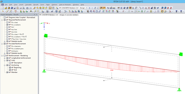
Design Using Result Member
This option should only be applied as of the ratio h/l ≤ 0.5, otherwise the lever arm is assumed to be favorable.< 0.5, otherwise the lever arm is assumed to be favorable. For the result evaluation and design, a horizontal result member is created in the center of gravity. A rectangular cross-section with the dimensions of the deep beam is specified. You should only select the corresponding surface in the detail settings of the result member. Now, the RF-CONCRETE Members add-on module can perform the member design on the result beam with the integrated internal forces of the deep beam.
Interpretation and Conclusion
Both results may differ substantially, depending on the geometry and loading. The main reason is the different assumption of levers in the design. In the case of surface design, a smaller lever arm results in the strain distribution, and thus causes larger required reinforcement.
When using the result member, you don't need to create several sections and determine the bending reinforcement manually. In addition, the reinforcement is arranged correctly.