You can calculate this steel temperature, for example, by means of a parametric temperature-time curve, as given in the Annex of DIN EN 1991-1-2. In the following text, we will explain and apply the calculation using the parametric temperature-time curve.
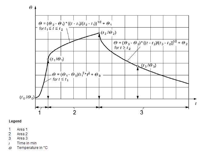
If parametric fire exposure is used as a fire scenario, the load reduction effect of the structural component must be ensured. There must be no failure of the component during the entire fire phase, including the cooling phase or within a required resistance period. Annex A of EN 1991-1-2 provides a parametric temperature-time curve. This fire scenario is no longer permitted in Germany, as the binding National Annex to EN 1991‑1‑2 must be applied. This scenario was replaced by design fire. With this curve, a possible fire scenario can be described completely, from the development phase to the full fire phase to the decay phase.
The curve sections are limited by distinctive points that result in the distribution of the rate of heat release. However, when determining the temperature values, it is necessary to distinguish between ventilation-controlled fires and fire load-controlled fires. Moreover, the application of this natural fire model is limited. It applies to floor spaces up to 400 m² and a height of up to 6 m. For ventilation-controlled design fires, the characteristic value of the maximum heat release rate may be calculated according to the following equations.
To calculate the temperature in the steel cross-section, you can use Microsoft Excel, for example. Under Downloads, you will find an Excel macro that can calculate the temperature. You can use the calculated value directly in the add-on module.
Calculation Process
The program first calculates the coating area, the opening factor, and the individual thermal penetration coefficients from the initial values, which are then averaged. A distinction is now made as to whether the fire is ventilation-controlled or fire load-controlled. The program distinguishes the fire type independently by comparing Qmax,v and Qmax,f. In the next step, the individual time periods and the corresponding temperatures are calculated using a reference fire load density q = 1,300 MJ/m².
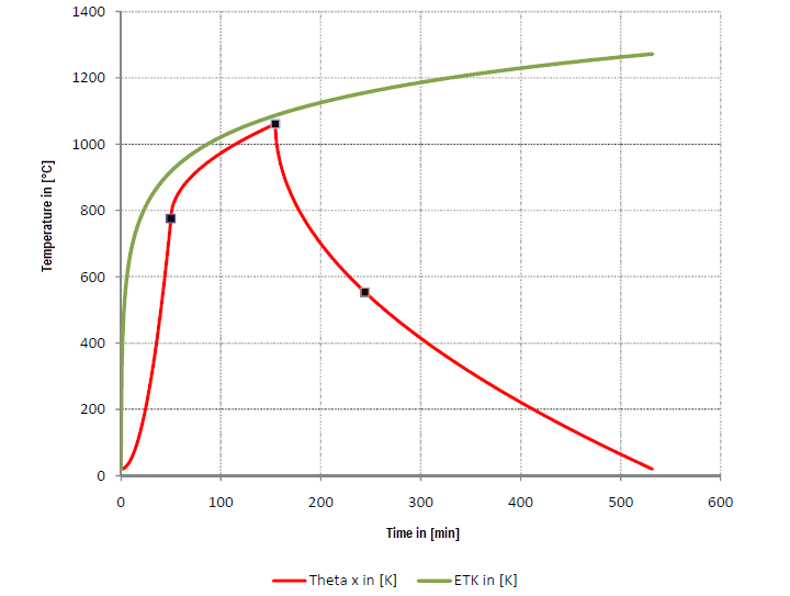
After calculating the reference temperature ranges, a comparison with the available fire load and the reference fire load follows in order to calculate the actually available time ranges and the corresponding temperatures. The individual points are calculated by means of a loop. Additionally, the standard temperature curve (ETK) is included in the program to obtain an immediate comparison with the natural fire scenario.
Calculation Results
The calculation shows that the natural fire burns more slowly than the ETK, although a very high fire load density was selected for the natural fire model. The heating of the fire chamber is also not as fast as the ETK, which is closer to reality. The duration of a natural fire scenario is usually significantly longer than required because it always includes a cooling-off phase. This cooling-off phase includes the burning-out of the fire compartment and can be significantly reduced by extinguishing processes, for example.