In computational fluid dynamics (CFD), complex surfaces that are not completely solid can be modeled using porous or permeability media. In the real world, examples of such surfaces include windbreak fabric structures, wire meshes, perforated facades and claddings, louvers, tube banks (stacks of horizontal cylinders), and so on.
Models of these structures can have such a complicated geometry that it is impossible to generate mesh efficiently for them; the resultant mesh might be exceedingly fine or poor quality in certain situations. In such conditions, the computation will either be wrong or it will take a significant amount of time using supercomputers. As a result, employing a model of a medium that allows flow passage is strongly recommended when dealing with these kinds of structures.
Here, we are going to explain step by step how to use the permeable surface feature in RWIND 2:
Step 1: Modeling Exact Geometry with Porosity in RWIND
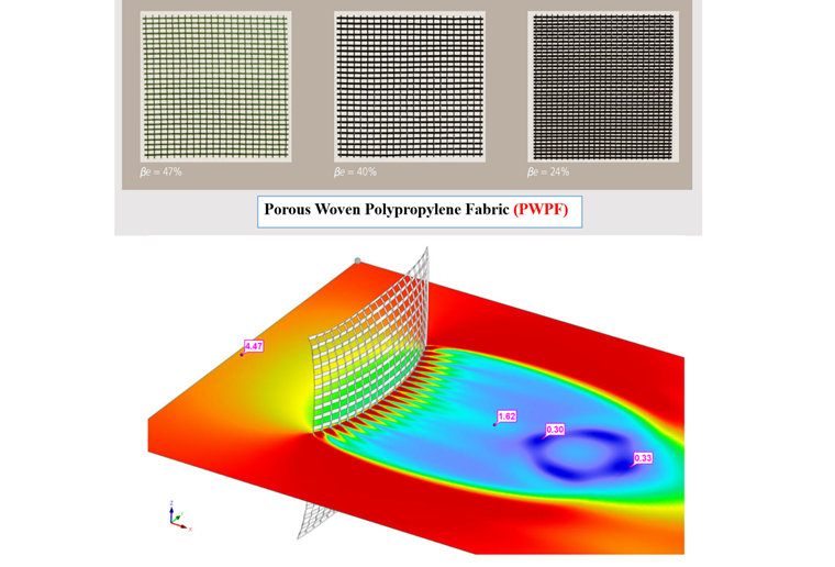
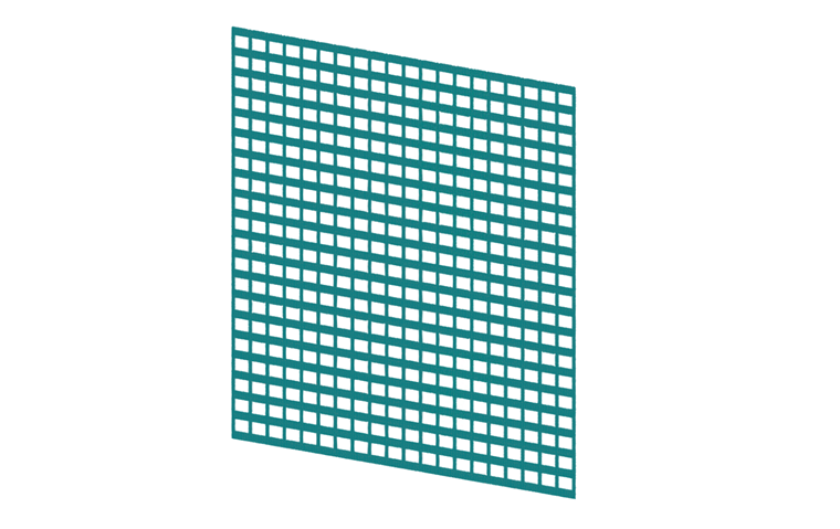
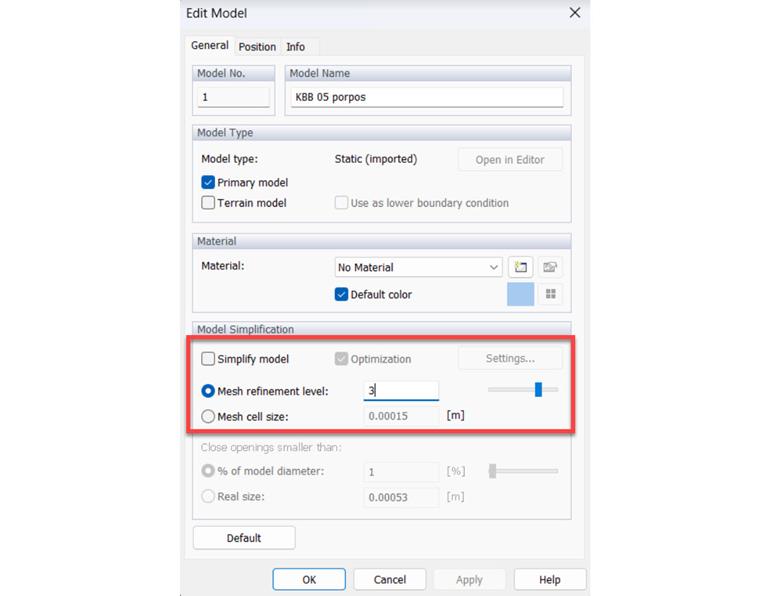
The exact model of geometry with specified porosity (here 40% porosity is considered) needs to be simulated (Image 2). For the implementation of the exact geometry, the option of the simplified model should be unchecked, and the mesh refinement level needs to be increased (Image 3).
Step 2: Simulation Setup
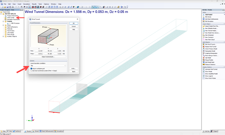
The whole cross-section of the simulation domain should be filled by the porous surface in order to let flow pass inside the porous section. The lower boundary condition of the wind tunnel needs to be set as slip to really see the pressure loss of the porous surface (Image 4). In this way, more precise pressure drop values will be obtained relevant to the porous surface.
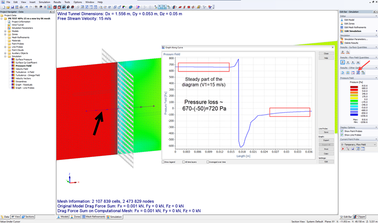
Step 3: Two Wind Simulations with Different Wind Speeds
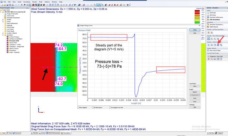
Here, 5 m/s and 15 m/s are considered as two different wind speeds. After simulations, we need to obtain pressure loss data using a graph along the line probe option in RWIND (Images 5, 6). It is very important to consider the steady part of the pressure field diagram to avoid the effects of local pressure fluctuation, particular position, and so on.
Step 4: Darcy-Forchheimer Calculator
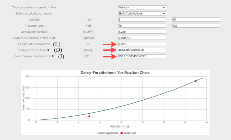
To obtain the required input parameters in RWIND, such as the Darcy coefficient (D) and the Inertial coefficient (I), we can use the Darcy-Forchheimer Calculator (
Darcy-Forchheimer Calculator
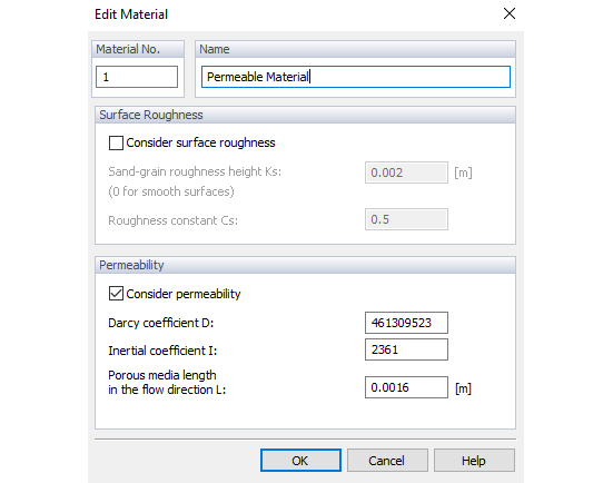
); the required information is shown in Image 7. After entering the input data, you can obtain the Darcy coefficient (D) and the Forchheimer contribution (F), which is equivalent to the Inertial coefficient (I) in RWIND; also, L is the permeable media length in the flow direction (here the thickness of the surface is = 0.0016 m). Finally, you can substitute all parameters in the RWIND table of permeable surfaces (Image 8).