


1. Introduction:
Wind loading is a critical component in the design of any structure, particularly for main wind force–resisting systems (MWFRS). The ASCE 7-22 [1] standard outlines several load cases that account for varying wind directions and building torsional effects.
Historically, RFEM 6’s Wind Load Wizard has allowed for the automatic generation of wind loads according to ASCE 7 for the traditional Cases 1 and 3, which represent the typical load scenarios for wind acting directly on the main faces of a structure.
With the latest update, RFEM 6 now supports Cases 2 and 4, which account for torsional load effects due to non-uniform wind pressures across the diaphragm. This enhancement allows users to generate more realistic wind load effects based on ASCE 7-22, especially for irregular or flexible diaphragm structures.
2. Understanding ASCE 7-22 Wind Load Cases
According to ASCE 7-22, Chapter 27, wind load cases for MWFRS are defined as follows:
- Case 1: Windward and leeward walls loaded simultaneously, no torsion (positive internal pressure).
- Case 2: Same as Case 1 but includes torsional load due to wind acting eccentrically on the building (positive internal pressure).
- Case 3: Reverse direction of Case 1 (negative internal pressure).
- Case 4: Reverse direction of Case 2 (negative internal pressure with torsion).
While Cases 1 and 3 represent symmetric pressure distributions, Cases 2 and 4 apply a torsional moment to the structure to simulate wind pressure variation across the width of the building.
3. Implementation in RFEM 6
3.1 Automatic Diaphragm Detection
RFEM 6’s Wind Load Wizard now automatically detects defined diaphragms in the structural model. This can occur in two ways:
- Through the Building Model Add-on, which defines diaphragms automatically at each floor level.
- By manually defining a rigid link diaphragm using the Rigid Link tool in the model.
Once a diaphragm is detected, the Wind Load Wizard evaluates the eccentricity of the wind pressure across the diaphragm to determine the torsional moment that needs to be applied in accordance with ASCE 7 Cases 2 and 4.
3.2 Load Case Generation
When generating wind loads according to ASCE 7-22, RFEM 6 will now create the following load cases automatically:
- Case 1: Wind in direction A-B (e.g., 180°) — standard pressure distribution.
- Case 2: Wind in direction A-B with torsional eccentricity.
- Case 3: Wind in direction B-A — reverse pressure distribution.
- Case 4: Wind in direction B-A with torsional eccentricity.
Each case applies the corresponding external pressure coefficients (Cp) and internal pressure coefficients (GCpi) per Chapters 26 and 27, while the torsional moment for Cases 2 and 4 is applied directly to the detected diaphragm plane.


For the verification example in the next section, some directions and load cases have been disabled for the purpose of simplifying the example and model.
4. Verification Example
To validate this new functionality, a simple rectangular building with a gable roof (shown below) was modeled in RFEM 6 and compared against hand calculations following ASCE 7-22 Chapters 26 and 27.
| Parameter | Symbol | Value |
|---|---|---|
| Building width | B | 32 ft |
| Building length | L | 40 ft |
| Eave height | he | 20 ft |
| Ridge height | hr | 30 ft |
| Mean roof height | hm = (he + hr)/2 | 25ft |
| Roof slope | θ | ≈33° |
4.1 Determine Design Wind Pressure Parameters
Following ASCE 7-22 Section 26.10:
For this example, there is qz for the windward walls following
- Risk Category III
- V=107 mph
- Kz = 0.57 (Exposure B, from 0 to 15 feet)
- Kz = 0.62 (Exposure B, at 20 feet)
- Kh = 0.66 (Exposure B, at 25 feet)
- Kzt = 1.0
- kd = 0.85
- Ke = 1.0
- G = 0.85
4.2 External Pressure Coefficients
From ASCE 7-22 Fig. 27.3-1 (gable roof, 18° slope):
| Surface | Cp |
|---|---|
| Windward wall | +0.8 |
| Leeward wall | -0.5 |
| Side walls | -0.7 |
| Roof (windward) | -0.12 |
| Roof (leeward) | -0.6 |
4.3 Design Pressures
Assuming internal pressure coefficient GCpi = +/- 0.18
| Surface | Cp | GCpi | p+ (psf) | p- (psf) |
|---|---|---|---|---|
| Windward Wall (0-15 ft) | +0.8 | +-0.18 | 6.70 | 12.62 |
| Windward Wall (20 ft) | +0.8 | +-0.18 | 7.54 | 13.423 |
| Leeward Wall | -0.5 | +-0.18 | -9.92 | -4.00 |
| Side Wall | -0.7 | +-0.18 | -12.82 | -6.91 |
| Roof Windward | -0.23 | +-0.18 | -6.25 | -0.25 |
| Roof Leeward | -0.6 | +-0.18 | -11.34 | -5.42 |
4.4 Design Torsional Moments
Torsional Moment about Z axis (+GCpi)
Case 2:
Case 4:
5. Compare with RFEM 6 Wind Load Wizard
In RFEM 6, use the Wind Load Wizard with ASCE 7-22 and the same parameters:
- The program automatically calculates qz and qh based on the mean roof height and the height of the walls.
- The Cp values were assigned to each surface based on the orientation and slope of the walls and roof.
- For Cases 1 and 3, symmetric pressures were generated.
- For Cases 2 and 4, the diaphragm eccentricity was detected, and an additional torsional moment was applied per ASCE 7-22 27.3-8
The resulting pressures and load distribution from RFEM 6 matched closely with the hand-calculated values, confirming the accuracy of the implementation. Minor differences (≤ 5%) can be attributed to the program's more precise geometric sampling of surface elevations and pressure zones.
Result comparison between hand calculations and RFEM 6:
5.1 Design Pressures from RFEM 6
The following values are taken from RFEM 6, more specifically Case 1 and the positive/negative internal pressure. The comparison will be made to the analytical values calculated by hand from section 4 of this article. The model file can be found at the bottom of the bottom of the page for individual comparison:
- Risk Category III
- V = 107 mph
- Kz = 0.57 (Exposure B, from 0 to 15 feet)
- Kz = 0.62 (Exposure B, at 20 feet)
- Kh = 0.6565 (Exposure B, at 25 feet)
- Kzt = 1.0
- kd = 0.85
- Ke = 1.0
- G = 0.85
Note: qz is not shown in the Wind Load Wizard
Assuming internal pressure coefficient GCpi = +/- 0.18
| Surface | Cp | GCpi | p+ (psf) | p- (psf) |
|---|---|---|---|---|
| Windward Wall (0-15 ft) | +0.8 | +-0.18 | 6.761 | 12.649 |
| Windward Wall (20 ft) | +0.8 | +-0.18 | 7.535 | 13.460 |
| Leeward Wall | -0.5 | +-0.18 | -9.895 | -4.007 |
| Side Wall | -0.7 | +-0.18 | -12.675 | -6.787 |
| Roof Windward | -0.23 | +-0.18 | -6.193 | -0.305 |
| Roof Leeward | -0.6 | +-0.18 | -11.285 | -5.397 |
5.3 Design Torsional Moments from RFEM 6
Torsional Moment about Z axis (+GCpi)
In RFEM 6, the torsional moment is calculated internally and parameters are not shown. The reason is that the calculation required for this is complex and would be difficult to show in the dialog box.
The image below shows a small example of the way RFEM 6 performs the calculation:
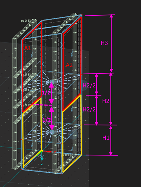
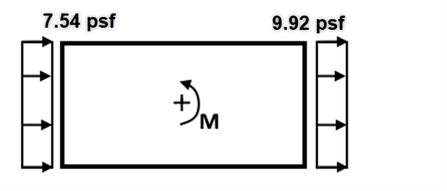
M = 7.54 * A1 * 0.15 * b1 + 9.92 * A2 * 0.15 * b2
A1 ... area of load on diaphragm on windward side
A2 ... area of load on diaphragm on leeward side
b1 ... width of building on windward side
b2 ... width of building on leeward side
Here are the moments for Cases 2 and 4 that RFEM 6 has calculated:
Case 2:
Mz,2 = 60.66 kip-ft
Case 4:
Mz,4 = 80.84 kip-ft
6. Conclusion and Result Comparison
The addition of Cases 2 and 4 in RFEM 6 represents a significant advancement in automated wind load generation according to ASCE 7-22. By detecting diaphragms and applying torsional effects automatically, engineers can now:
- Capture the full range of MWFRS load cases (1-4) without manual input
- Ensure compliance with ASCE 7-22 Chapters 26 and 27.
- Improve modeling efficiency and design reliability.
This verification example demonstrated that the RFEM 6 Wind Load Wizard produces results consistent with manual ASCE 7-22 calculations, providing users with confidence in both accuracy and automation. This can be seen in the table below, which compares the values calculated by hand with the values found in RFEM 6:
Note: Values such as Kh and Cp are rounded in a hand calculation, causing some discrepancy. RFEM 6 uses exact values.
Positive Internal Pressure (+GCpi)
| Surface | Analytical Pressure (psf) | RFEM 6 Pressure (psf) | RFEM/Analytical |
|---|---|---|---|
| Windward Wall (0-15 ft) | 6.70 | 6.761 | 1.01 |
| Windward Wall (20 ft) | 7.54 | 7.54 | 1.00 |
| Leeward Wall | -9.92 | -9.895 | 1.00 |
| Side Wall | -12.82 | -12.675 | 0.99 |
| Roof (Windward) | -6.25 | -6.193 | 0.99 |
| Roof (Leeward) | -11.34 | -11.285 | 1.00 |
Negative Internal Pressure (-GCpi)
| Surface | Analytical Pressure (psf) | RFEM 6 Pressure (psf) | RFEM/Analytical |
|---|---|---|---|
| Windward Wall (0-15 ft) | 12.62 | 13.423 | 1.00 |
| Windward Wall (20 ft) | 10.50 | 12.649 | 1.00 |
| Leeward Wall | -4.00 | -4.01 | 1.00 |
| Side Wall | -6.91 | -6.787 | 0.98 |
| Roof (Windward) | -0.33 | -0.305 | 0.92 |
| Roof (Leeward) | -5.42 | -5.397 | 1.00 |
Design Torsional Moments (+GCpi)
| Case | Analytical Moment (kip-ft) | RFEM 6 Moment (kip-ft)) | RFEM/Analytical |
|---|---|---|---|
| 2 | 63.25 | 60.66 | 0.96 |
| 4 | 89.82 | 80.84 | 0.90 |

