461 Results
View Results:
Sort by:
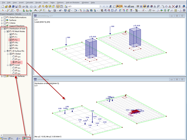
"Distribution of load" represents a load actually applied to the system of FE mesh points or FE surfaces. The FE mesh size plays an important role in the loading in the case of line loads and free loads in particular.

Diagonals of double angles are used for pipe bridge construction and for truss girders, among other things. They are usually subjected to tension, but it is necessary to transfer them in smaller compression forces with regard to the load application. In the case of slender diagonals in particular, you should also consider the bending due to self‑weight.

The new RF‑/DYNAM Pro - Natural Vibrations module has been available since RFEM version 5.04.xx and RSTAB version 8.04.xx were released. Masses can now be imported directly from load cases and load combinations.
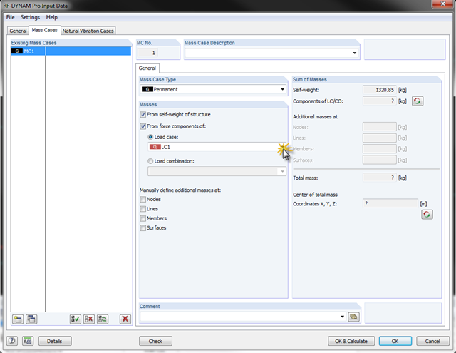
In RF-/DYNAM Pro - Natural Vibrations, it is possible to transfer complete load cases/load combinations as masses. To do this, you can simply save the load case or the load combination to be considered as a mass case in the add‑on module.

A previous article describes the design of double angles. It deals with analysis performed on a single member.
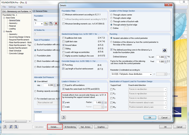
In RFEM and RSTAB, the internal forces of individual load combinations are determined according to the second-order analysis by default. If you use the RF‑CONCRETE add‑on module for stability analysis of reinforced concrete columns, you can change the calculation method of LCs to the linear static analysis, since the effects of the second‑order analysis are already considered in the calculation according to the model column method in RF‑CONCRETE Columns (nominal curvature method).
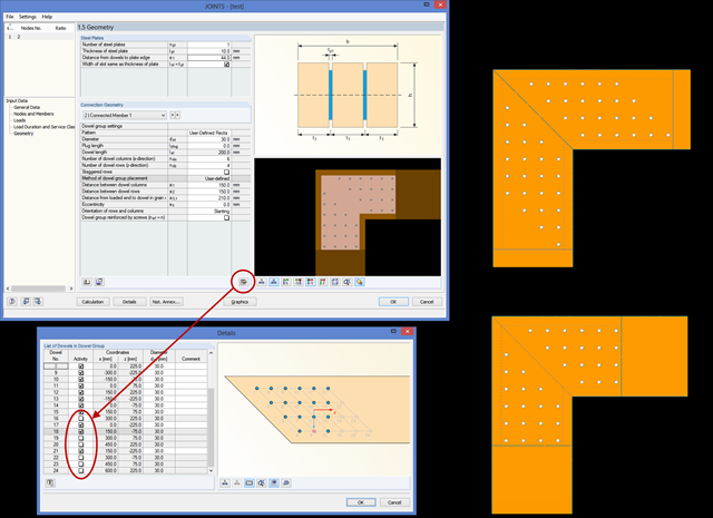
In RF‑/JOINTS Timber, you can remove an individual dowel from the calculation, thus creating any dowel layout. The calculation disregards these removed dowels for the ultimate limit state design, as well as for the net timber cross‑section analysis and the rotational spring stiffness determination.
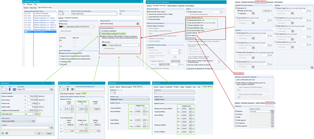
In RF-/DYNAM Pro - Natural Vibrations, you can import axial forces and stiffness modifications from any Load Case (LC) or Load Combination (CO). You can modify material, cross‑section, member, and surface properties and activate these modifications in the LC/CO calculation parameters.
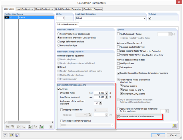
With RFEM 5.04, there are new options for the system analysis (critical load factors) of load cases and load combinations in the calculation parameters of the RF‑STABILITY add‑on module: ~ The load increment is not closed due to stability problems, but optionally also due to predetermined deformation limits. ~ The calculation method is applicable to all nonlinear calculations. ~ You can define an initial load (LC/CO) that is not increased (for example, self-weight). ~ The "Refinement of the last load increment" option provides an efficient option to determine the critical load factor as precisely as possible.
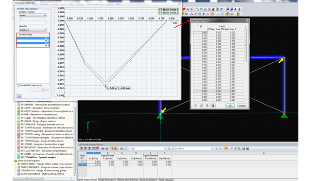
RF-/DYNAM Pro - Forced Vibrations provides the option of a time course monitor. During the evaluation process, you can compare several graphs directly in the program. In addition, you can transfer the figures to the printout report or export them directly to Excel as a value table.
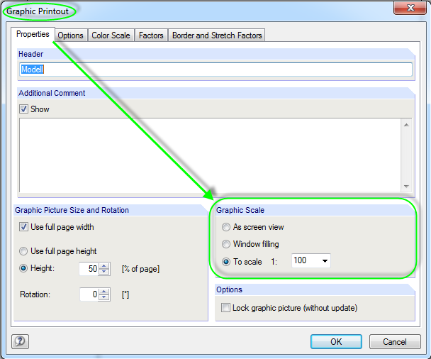
A graphical documentation of the structural analysis results facilitates the result interpretation tremendously. There are various scale options available for printing graphics in the printout report.
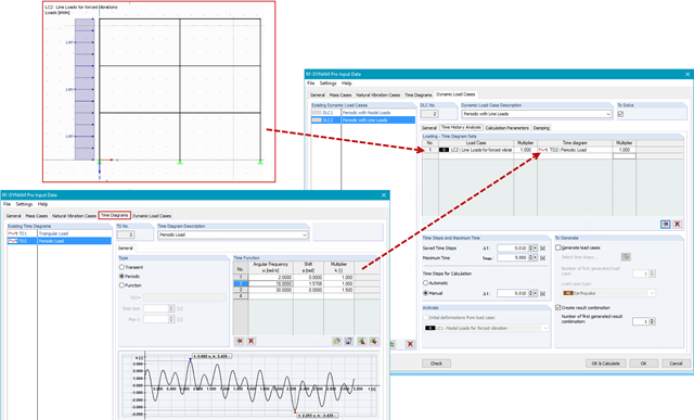
In RF-/DYNAM Pro - Forced Vibrations, you combine static load cases with time diagrams to define the type of excitation of your structure. This way, you can use not only nodal loads, but also use line, surface, free, or generated loads in the time history analysis.
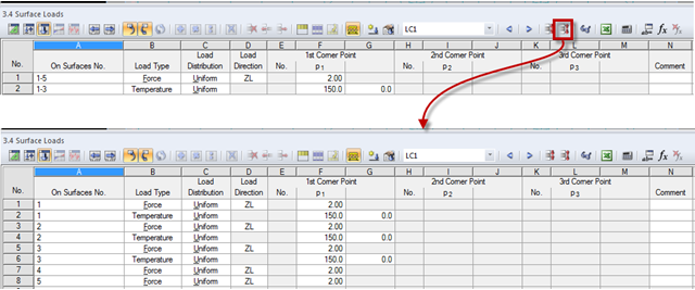
The load tables provide a simple option to control the applied loads. Dividing loads into individual lines is expedient. After dividing loads into the load table, the load data are displayed by a structural element (nodes, members, lines, surfaces, or solids). Thus, the load data analysis of each structural element is facilitated. The load case data can be compressed later.
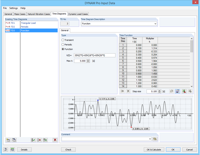
In RF-/DYNAM Pro - Forced Vibrations, you can define time diagrams directly as functions in an edit field. The parameter t is reserved for the time steps, but apart from that, all parameters as defined in the "Edit Parameter" dialog can be used in RF‑/DYNAM Pro.
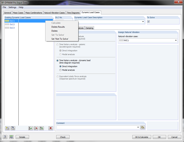
In RF-/DYNAM Pro, you can now keep the existing results. For example, if you work with several dynamic load cases, you can calculate or modify the individual dynamic load cases while retaining the unchanged results of the other dynamic load cases.
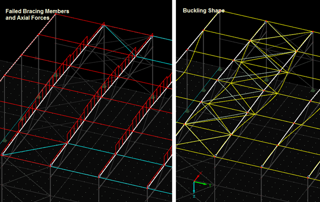
The previous post on this topic describes instabilities that may occur when using tension members. The example shown refers primarily to wall stiffening. Now, instability error messages can also refer to nodes within the range of supports. Truss girders and support trusses are especially susceptible to this. What causes the instability here?
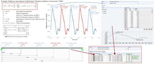
To simulate an excitation that varies over time and changes its position, you can combine several loading time diagrams in RF‑/DYNAM Pro - Forced Vibrations.
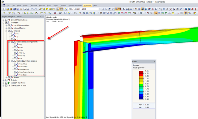
RFEM 5.04.xx allows for graphical visualization of normal and shear stress of members (this feature is available only if the RF‑STEEL add‑on module is licensed).
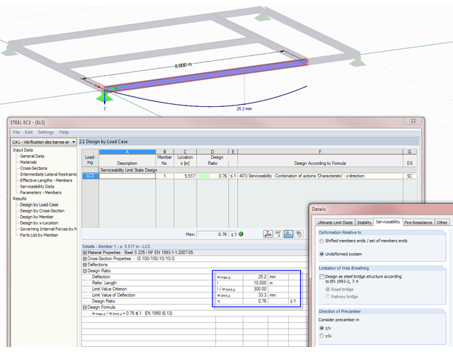
Not only do RF-/STEEL EC3 and RF-/TIMBER Pro perform cross-section designs and stability analyses, they allow you to perform serviceability limit state designs. For this, it is possible to relate the deformation to the undeformed initial system or to shifted members ends.

In January 2015, DIN Committee NA 005‑08‑23 Steel Bridges applied the introduction of a modification in equation 10.5 of DIN EN 1993‑1‑5. This involves the interaction of longitudinal and transverse pressure in a buckling analysis. Now, the interaction equation provides for auxiliary factor V, which is calculated from the reduction factors of the longitudinal and transverse stresses.