7 Results
View Results:
Sort by:
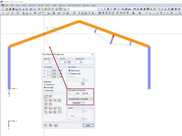
For a frame trussed from below, compression members are to be modelled perpendicular to the inclined beam. The member length and the intersection with the horizontal beam are defined.
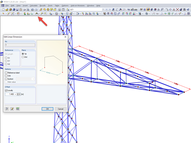
In RFEM and RSTAB, you can have contiguous dimension lines that are inclined in space.
Friction plays an important role in practice. Without friction, the brakes of cars would be useless, objects on inclined planes would just slide away, and prestressed bolt connections would be impossible.
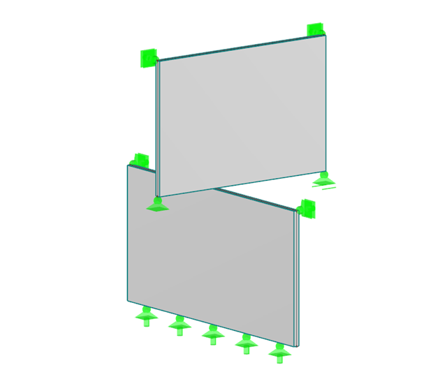
This article describes how to determine the contact force between two objects behaving like walls that are diagonally inclined at a certain angle on top of each other. Define a nodal release to determine this contact force. Since a nodal release requires certain conditions, this article shows two examples.

If a canopy roof (for example, a filling station roof) should be designed, a load determination with regard to Section 7.3 of EN 1991-1-4 is required. This article shows the design of a slightly inclined troughed roof, with an example.

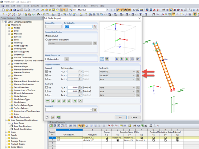
Nodal supports are usually defined with regard to the global axis system. However, it is sometimes necessary to rotate the nodal support. For example, for a floor slab with a pile foundation. For geological reasons, the piles do not rest in the ground vertically, but in an inclined position. Each end point of the piles has a nodal support that can only absorb forces along the pile foundation direction. Therefore, rotating the nodal support is required. Various options for this are described in previous posts.
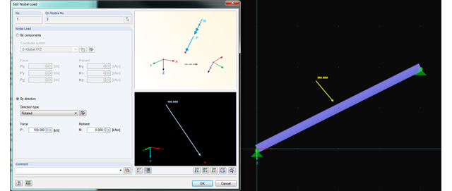
In RFEM and RSTAB, you can now rotate nodal loads or apply them on member axes. Thus, inclined members can also be loaded with nodal loads perpendicularly or along the member axis.