7 Results
View Results:
Sort by:

The design of cross-sections according to Eurocode 3 is based on the classification of the cross-section to be designed in terms of classes determined by the standard. The classification of cross-sections is important, since it determines the limits of resistance and rotation capacity due to local buckling of cross-section parts.

The RF-/LIMITS add-on module allows you to compare the ultimate limit state of members, member ends, nodes, nodal supports, and surfaces (RFEM only) by means of a defined ultimate load capacity. Furthermore, you can check nodal displacements and cross-section dimensions. In this example, the column bases of a carport are to be compared with the maximum allowable forces specified by the manufacturer.
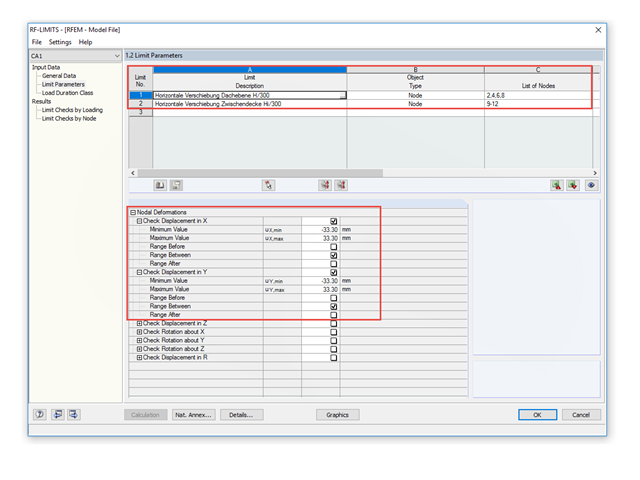
To control the lateral displacements of a model, you can use the RF-/LIMITS add‑on module. This add‑on module allows you to, for example, run a serviceability limit state analysis to find horizontal nodal deformations and to set it against a limit value.

The classification of cross-sections is intended to determine the limits of resistance and rotational capacity due to local buckling of cross-section parts. In EN 1999‑1‑1, 6.1.4.2 (1), four classes are defined.
Computer technology has a firm grip on digital structural analysis and design. With each new development, the planners involved are able to increase the limits of what is feasible.

The form-finding process in RF-FORM-FINDING displaces the corner nodes of FE elements of a membrane surface in space until the defined surface stress is in equilibrium with the boundary conditions. This displacement is independent of the element geometry. In the case of elements with four corner nodes, the free displacement may cause spatial drilling in the element plane and thus exceed the validity limits of the calculation; therefore, triangular elements are generally recommended for form‑finding systems. Triangular elements remain independent of the corner node displacement and stay within the calculation limitations.
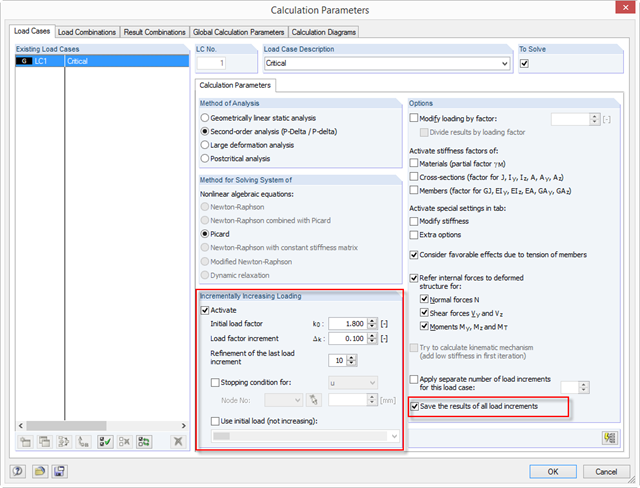
With RFEM 5.04, there are new options for the system analysis (critical load factors) of load cases and load combinations in the calculation parameters of the RF‑STABILITY add‑on module: ~ The load increment is not closed due to stability problems, but optionally also due to predetermined deformation limits. ~ The calculation method is applicable to all nonlinear calculations. ~ You can define an initial load (LC/CO) that is not increased (for example, self-weight). ~ The "Refinement of the last load increment" option provides an efficient option to determine the critical load factor as precisely as possible.