- Class 1 cross-sections are those that can form a plastic hinge with the rotation capacity required for plastic analysis without reduction of the resistance.
- Class 2 cross-sections are those that can develop plastic moment resistance, but have limited rotation capacity because of local buckling.
- Class 3 cross-sections are those in which the calculated stress in the extreme compression fiber of the aluminum member can reach its proof strength, but local buckling is liable to prevent development of the full plastic moment resistance.
- Class 4 cross-sections are those in which local buckling will occur before the attainment of proof stress in one or more parts of the cross-section.
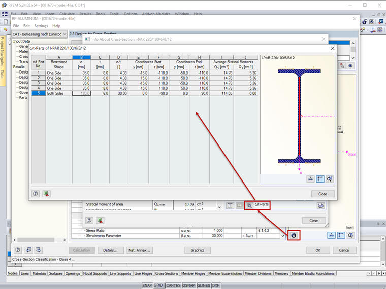
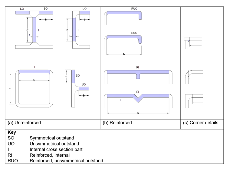
Basic Types of Cross-Section Parts
A cross-section's classification depends on the width/thickness ratio b/t of its parts subjected to compression. According to EN 1999-1-1 [1], 6.1.4.2 (6), thin-walled parts are classified into the following basic types.
- Flat outstand parts
- Flat internal parts
- Curved internal parts
These parts can be unreinforced, or reinforced by longitudinal stiffening ribs, edge lips, or bulbs (Image 1).
Slenderness Parameters
The susceptibility of an unreinforced flat part to local buckling is defined by the parameter β. According to EN 1999-1-1, 6.1.4.3 (1), it has the following values.
- Flat internal parts with no stress gradient or flat outstands with no stress gradient or peak compression at toe
- β = b / t | EN 1999-1-1, (6.1)
- Internal parts with a stress gradient that results in a neutral axis at the center
- β = 0.40 · b / t | EN 1999-1-1, (6.2)
- Internal parts with stress gradient and outstands with peak compression at root
- β = η · b / t | EN 1999-1-1, (6.3)
where
| b | Width of cross-section part |
| t | Thickness of cross-section |
| η | Stress gradient factor(1) |
| ψ | Ratio of the stresses at the edges of the plate under consideration related to the maximum compressive stress(2) |
(1)Coefficient for stress gradient given by the following expressions:
η = 0.70 + 0.30 · ψ for 1 ≥ ψ ≥ -1 | EN 1999-1-1, (6.4)
η = 0.80 / (1 - ψ) for ψ < -1 | EN 1999-1-1, (6.5)
(2)In general the neutral axis should be the elastic neutral axis, but in checking whether a section is Class 1 or 2, you are permitted to use the plastic neutral axis.
Slenderness parameters for flat stiffened cross-section parts are given in EN 1999-1-1, 6.1.4.3 (3).
EN 1999-1-1, 6.1.4.3 (4) contains information on slenderness parameters for flat-curved, unstiffened, internal cross-section parts restrained on both sides. EN 1999-1-1, 6.1.4.3 (5) deals with the slenderness parameters of thin-walled tubular sections.
Classification of Cross-Section Parts
The calculated slenderness parameters β must be compared with the limit values β1 to β3, which are determined according to EN 1999-1-1, Table 6.2 (see below).
- ε = √(250 / fo)
- fo in N/mm²
| Material Classification According to Table 3.2 | Internal Part | Outstand Part | ||||
|---|---|---|---|---|---|---|
| β1/ε | β2/ε | β3/ε | β1/ε | β2/ε | β3/ε | |
| Class A, without welds | 11 | 16 | 22 | 3 | 4.5 | 6 |
| Class A, with welds | 9 | 13 | 18 | 2.5 | 4 | 5 |
| Class B, without welds | 13 | 16.5 | 18 | 3.5 | 4.5 | 5 |
| Class B, with welds | 10 | 13.5 | 15 | 3 | 3.5 | 4 |
The classification distinguishes between bending beams and compression members. The following limits are defined in EN 1999-1-1, 6.1.4.4 (1).
Cross-section parts in bending beams
- β ≤ β1 → Class 1
- β1 < β ≤ β2 → Class 2
- β2 < β ≤ β3 → Class 3
- β3 < β → Class 4
Cross-section parts in compression members
- β ≤ β2 → Class 1 or 2
- β2 < β ≤ β3 → Class 3
- β3 < β → Class 4
Each cross-section part that is completely or partially subjected to compression must be assigned to a cross-section class. The cross-section part with the most unfavorable cross-section class determines the class of the entire cross-section. The classification of cross-sections for structural components with bending and longitudinal forces must be carried out separately for each loading component according to EN 1999-1-1, 6.3.3. No classification is required for the combined stress state.
Example
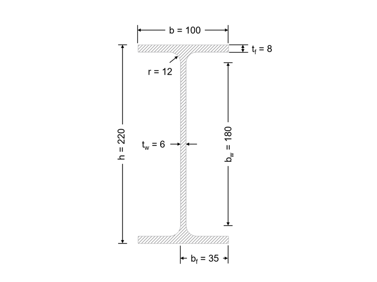
The classification is carried out for the I-section shown in Image 02 for pure bending and pure compression force.
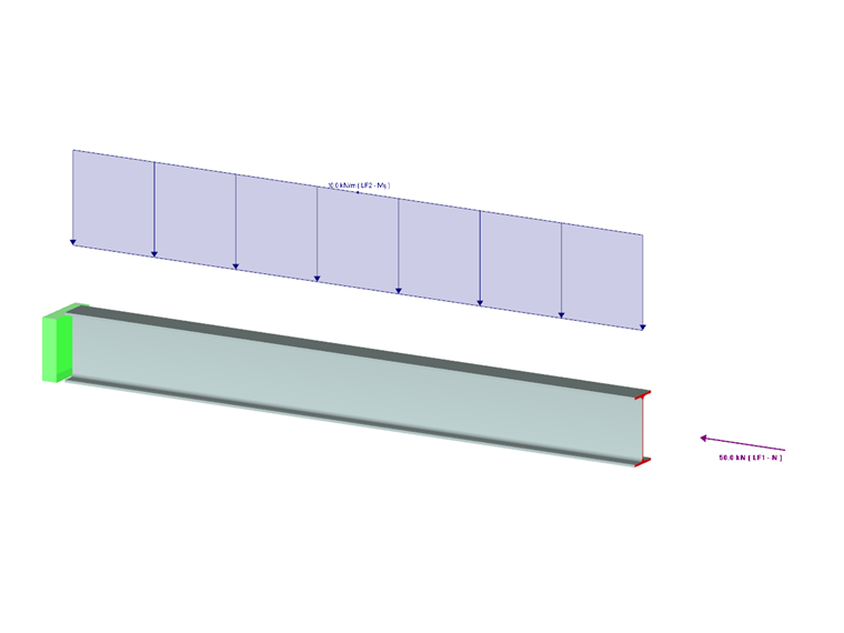
System and loading are shown in Image 03.
Material and Dimensions
- EN-AW 6082 (EP,ET,ER/B) T4 | EN 1999-1-1, Tabelle 3.2b
- fo = 110 N/mm²
- fu = 205 N/mm²
- Buckling class B
- ε = √(250 / fo) = √(250 / 110) = 1.508 | EN 1999-1-1, Table 6.2
- bw = h - 2 ∙ (tf + r) = 220 - 2 ∙ (8 + 12) = 180 mm
- bf = 0.5 ∙ (b - tw - 2 ∙ r) = 0.5 ∙ (100 - 6 - 2 ∙ 12) = 35 mm
Cross-Section Classification – Pure Bending
Web (internal, without welds, buckling class B)
- βw = 0.4 ∙ bw / tw = 0.4 ∙ 180 / 6 = 12 | EN 1999-1-1, (6.2)
- β1 = 13 ∙ ε = 13 ∙ 1.508 = 19.6 | EN 1999-1-1, Table 6.2
- βw = 12 < β1 = 19.6
The web is classified in cross-section Class 1.
Flange (cantilevered, without welds, buckling class B)
- βf = bf / tf = 35 / 8 = 4.38 | EN 1999-1-1, (6.1)
- β1 = 3.5 ∙ ε = 3.5 ∙ 1.508 = 5.28 | EN 1999-1-1, Table 6.2
- βf = 4.38 < β1 = 5.28
The web is to be classified in cross-section Class 1.
The entire cross-section is to be classified for pure bending in cross-section Class 1.
Cross-Section Classification – Pure Compression Force
Web (internal, without welds, buckling class B)
- βw = bw / tw = 180 / 6 = 30 | EN 1999-1-1, (6.1)
- β3 = 18 ∙ ε = 18 ∙ 1.508 = 27.14 | EN 1999-1-1, Table 6.2
- βw = 30 > β3 = 27.14
The web is classified in cross-section Class 4.
Flange (cantilevered, without welds, buckling class B)
- βf = bf / tf = 35 / 8 = 4.38 | EN 1999-1-1, (6.1)
- β2 = 4.5 ∙ ε = 4.5 ∙ 1.508 = 6.79 | EN 1999-1-1, Table 6.2
- βf = 4.38 < β2 = 6.79
The flange is to be classified in cross-section Class 1 or 2.
The entire cross-section is to be classified for pure compression force in cross-section Class 4.
RF-/ALUMINUM
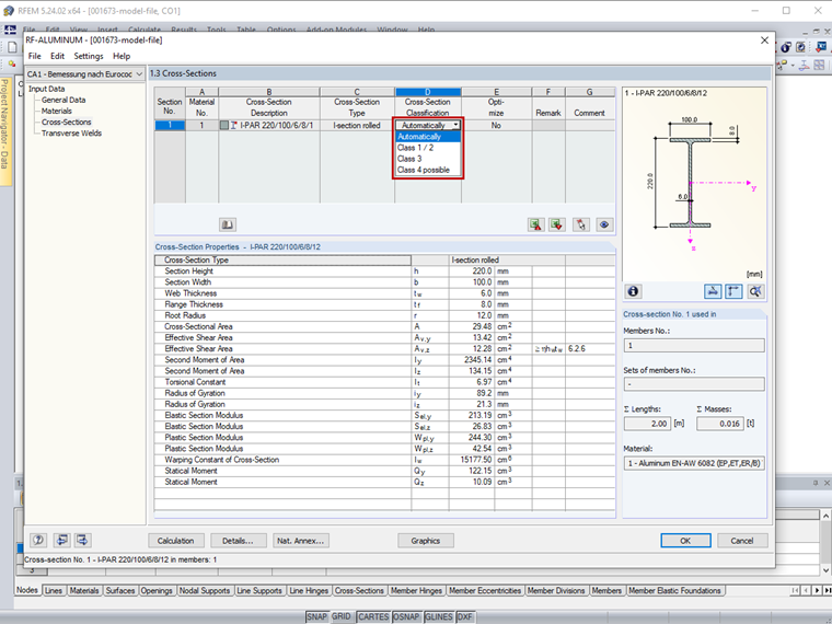
RF-/ALUMINUM determines the width/thickness ratios of the cross-section parts subjected to compression and performs the classification automatically. Alternatively, the cross-section class can be defined individually in the "Cross -Section Classification" list of the "1.3 Cross-Sections" window (Image 04). Cross-sections that are not completely covered by the standard specifications are classified as "General" in RF-/ALUMINUM and they are classified only into cross-section Class 3 or 4.
RF-/ALUMINUM only considers unstiffened cross-section parts according to EN 1999-1-1, Figure 6.1 (a) as well as thin-walled tubular sections according to EN 1999-1-1, 6.1.4.3 (5). Slightly curved, unstiffened, internal cross-section parts restrained on both sides according to EN 1999-1-1, 6.1.4.3 (4) can only be considered for the calculation performed with the simplified analytical method. The influence of stiffeners according to EN 1999-1-1, 6.1.4.3 (3) is not considered.
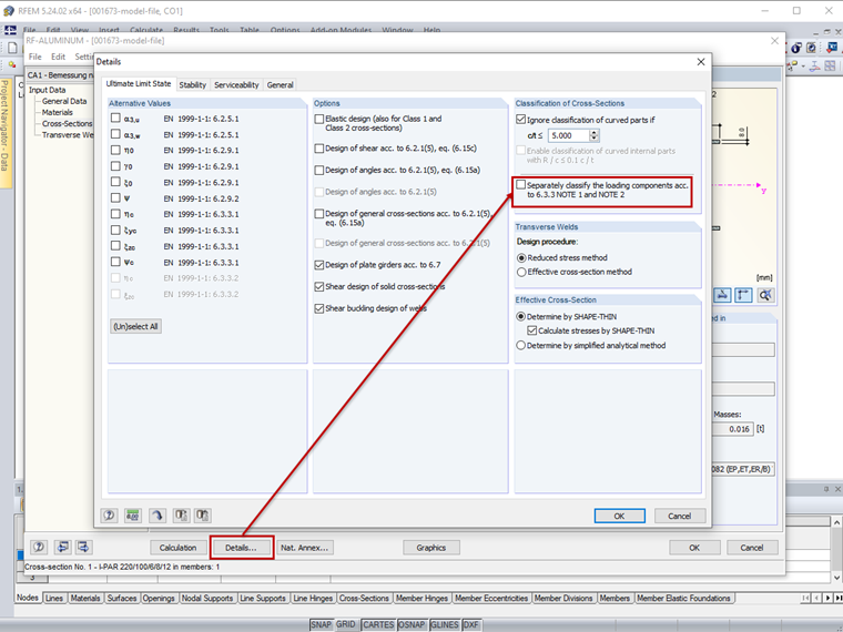
The classification of cross-sections for structural components with bending and longitudinal forces is carried out separately for each loading component in RF-/ALUMINUM according to EN 1999-1-1, 6.3.3. However, it is also possible to perform a classification for the combined stress state. To do this, deactivate the check box "Separately classify the loading components according to 6.3.3 NOTE 1 and NOTE 2" in the "Ultimate Limit State" tab of the "Details" dialog box (Image 05).
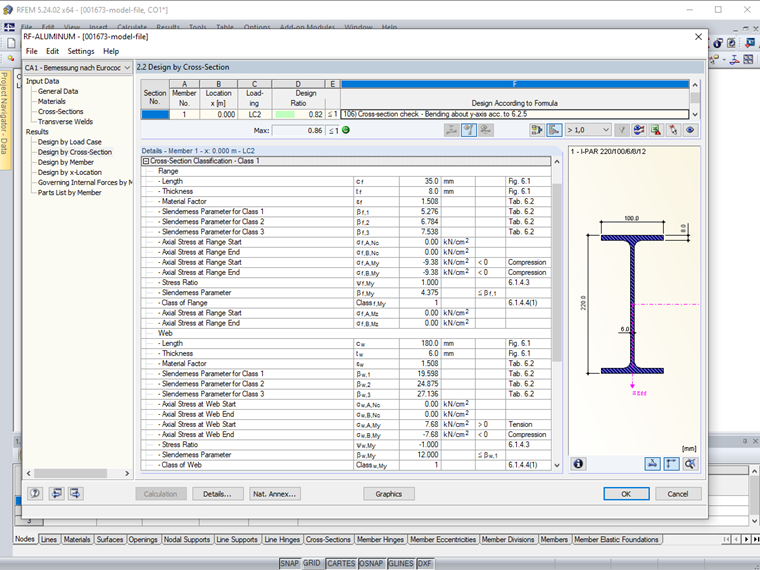
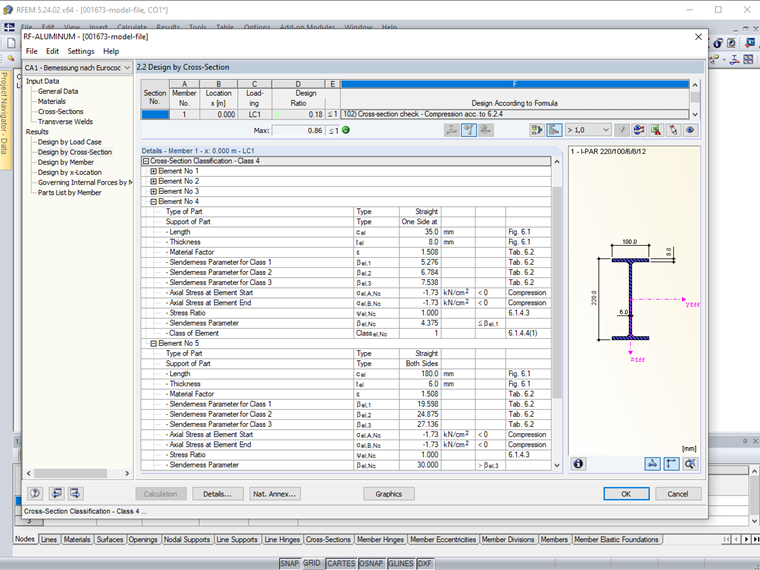
The cross-section classification in RF-/ALUMINUM is displayed in detail for each compression-loaded cross-section part among the intermediate values. The cross-section classification of this example for pure bending and pure compression is shown in Images 06 and 07.
The cross-section parts' numbering can be found in the "c/t-Parts" dialog box (Image 08).