17 Results
View results:
Sort by:

In accordance with Sect. 6.6.3.1.1 and Clause 10.14.1.2 of ACI 318-19 and CSA A23.3-19, respectively, RFEM effectively takes into consideration concrete member and surface stiffness reduction for various element types. Available selection types include cracked and uncracked walls, flat plates and slabs, beams, and columns. The multiplier factors available within the program are taken directly from Table 6.6.3.1.1(a) and Table 10.14.1.2.

Complex structures are assemblies of structural elements with various properties. However, certain elements can have the same properties in terms of supports, nonlinearities, end modifications, hinges, and so on, as well as design (for example, effective lengths, design supports, reinforcement, service classes, section reductions, and so on). In RFEM 6, these elements can be grouped on the basis of their shared properties and thus can be considered together for both modeling and design.

In the case of using slow‑curing concrete (usually for thick components), you can reduce the calculated minimum reinforcement by a factor of 0.85 to apply the load due to restraint, according to EN 1992‑1‑1, Section 7.3.2. However, a precondition for reduction is that the characteristic value of the strength development r = fcm2 / fcm28 does not exceed 0.3. Other key requirements for the application of this reinforcement reduction are specified explicitly in the final planning documents.

Supports contributing to a load reduction only under compression or tension can be defined as nonlinear supports in RFEM and RSTAB. It is not always easy for the user to select the correct nonlinearity for "failure under tension" or "failure under compression".
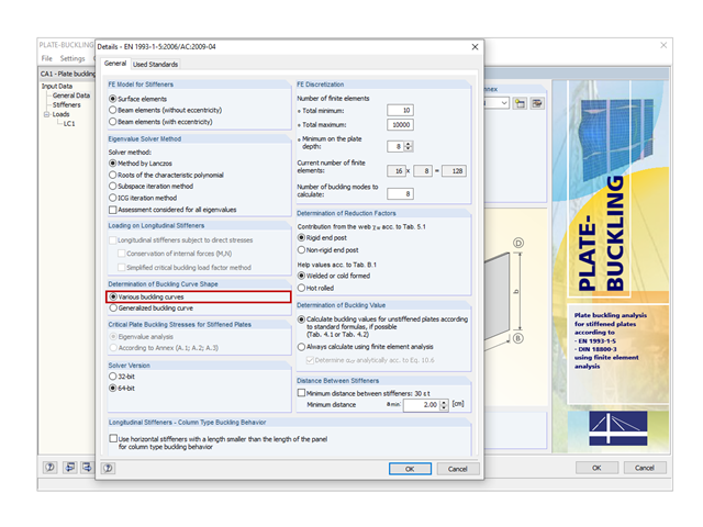
In PLATE‑BUCKLING 8, two options in the detail settings can be used to calculate the reduction factors of plate buckling.

When connecting tension-loaded components with bolted connections, the cross-section reduction due to the bolt holes must be taken into account in the ultimate limit state design. This article describes how the design of the tension resistance according to DIN EN 1993‑1‑1 can be performed with the net cross-section area of the tension member in the RF‑/STEEL EC3 add-on module.
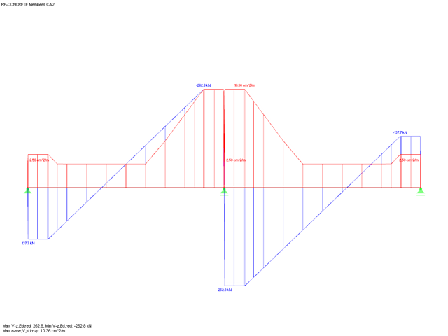
When performing shear force design in RF-CONCRETE Members and CONCRETE, you can reduce the acting shear force Vz according to EN 1992-1-1. The following article describes the reduction of the concentrated loads close to the support and the shear force design at the distance d from the support face for a uniform load.

In accordance with Sec. 6.6.3.1.1 and Sec. 10.14.1.2 of ACI 318-14 and CSA A23.3-14, respectively, RFEM effectively takes into consideration concrete member and surface stiffness reduction for various element types. Available selection types include cracked and uncracked walls, flat plates and slabs, beams, and columns. The multiplier factors available within the program are taken directly from Table 6.6.3.1.1(a) and Table 10.14.1.2.
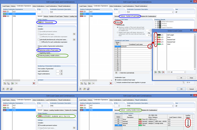
This post describes two practical examples, based on the Eurocodes, where the reduction of combinations is reasonable. There are a large number of various National Annexes as well as several material standards (EC 2 to EC 9) that are not in compliance with the rules for structural design (EC 0).
Requirements for the design of structural stability are given in the AISC 360 – 14th Ed. Chapter C. In particular, the direct analysis method provisions, previously located in Appendix 7 of the AISC 360 – 13th Ed., are described in detail. This method is considered an alternative to the effective length method, which in turn eliminates the need for effective length (K) factors other than 1.0.

In the case of tension connections with cleats subjected to unilateral loading, the external members (side timber) are loaded by an additional bending moment due to the eccentric load distribution. However, this fact is not mentioned in EN 1995‑1‑1 and is considered in the National Annex to DIN EN 1995‑1‑1 by the reduction of the tensile strength. This reduction depends on the pull-off strength of the fasteners.

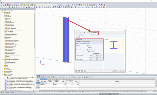
With RFEM version 5.06, member stiffnesses can be influenced by methods that are aligned with US steel construction standard ANSI/AISC 360-10. According to this standard, reduction factor τb must be considered for the determination of internal forces in all members of which the flexural resistance contributes to the model's stability. This coefficient depends on the axial force in the member: The larger the axial force, the larger τb is.

As of the program version X.06 of the RF‑/TIMBER Pro, RF‑/TIMBER AWC, and RF‑/TIMBER CSA add‑on modules, notches and cross‑section reductions can be considered in the design. The procedure is as follows:

In January 2015, DIN Committee NA 005‑08‑23 Steel Bridges applied the introduction of a modification in equation 10.5 of DIN EN 1993‑1‑5. This involves the interaction of longitudinal and transverse pressure in a buckling analysis. Now, the interaction equation provides for auxiliary factor V, which is calculated from the reduction factors of the longitudinal and transverse stresses.
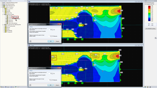
You can display the results on surfaces in a graphic. It may be useful to use the values on surfaces. Depending on the requirements, you can reduce the number of values considerably or adjust them to cover the entire structure. However, it is important to display the values that represent the local extreme values. In addition, it is necessary to determine the local extremes. This can be done by right-clicking this function in the Navigator.
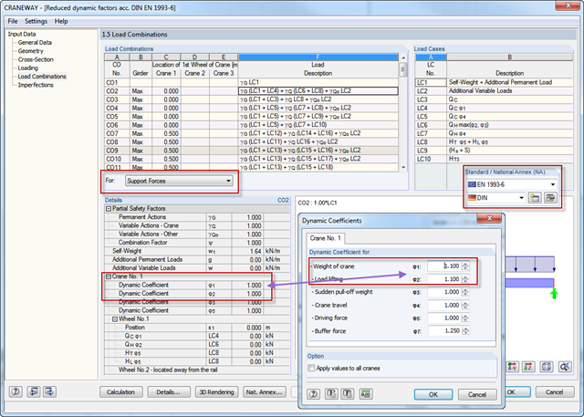
NCI to DIN EN 1993‑6, Part 2.3.1 allows reductions of dynamic coefficients for values ≧ 1.1. Therefore, you can use these reduced support loads for designing support and hanger structures. In CRANEWAY, if you select National Annex "DIN" and dynamic coefficients ≧ 1.1, the reduction is considered automatically.
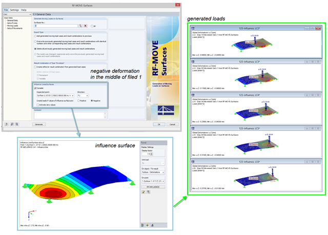
For the reduction of loads generated in RF‑MOVE Surfaces, you can consider the influence surfaces of a selected point. The influence surfaces are determined by RF-INFLUENCE. This procedure is useful in cases where only unfavorably acting loads should be considered. Depending on the unfavorable action, you should select the positive or negative direction.