
Are you afraid that your project will end in the digital tower of Babel? The Building Model add-on for RFEM supports you in your work on a construction project with several stories. It allows you to define a building by means of stories at specified elevations. You can adjust the stories in many ways afterwards and also select the story slab stiffness. Information about the stories and the entire model (center of gravity, center of rigidity) is displayed for you in tables and graphics.
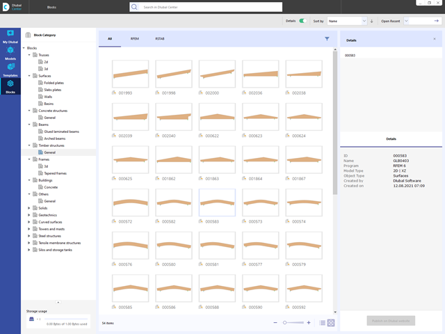
Are you looking for models for your design? Then you have come to the right place at the Dlubal Center. It contains an extensive database with partly parameterized models. These include, for example, trusses, glulam beams, tapered frames, or tower segments. You can import these models and, if necessary, modify them according to your individual requirements. Furthermore, you can save the models as a block for later use.
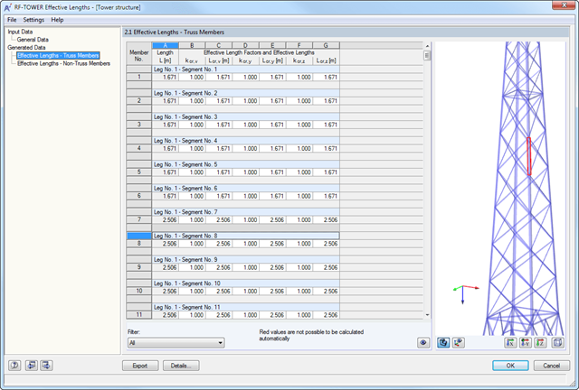
After generating the effective lengths, the results are displayed in clearly arranged tables. You can modify the effective lengths manually there.
The Export function transfers the effective lengths to the RF-/TOWER Design add-on module for further calculation. The complete module data are part of the RFEM/RSTAB printout report. The report contents and the extent of the results can be selected specifically for the individual designs.
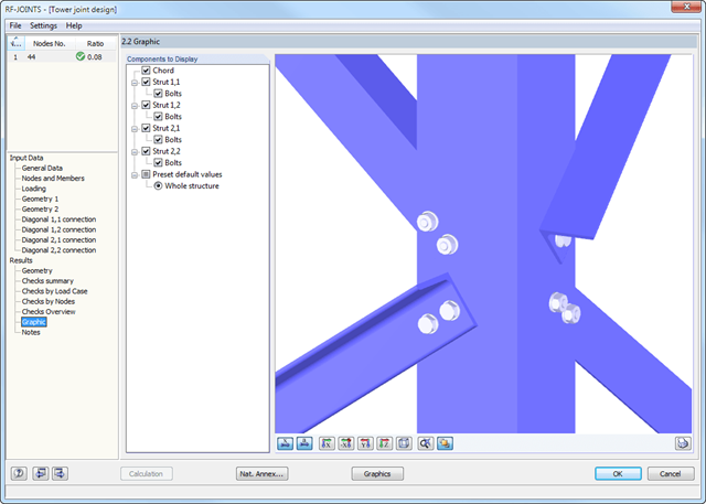
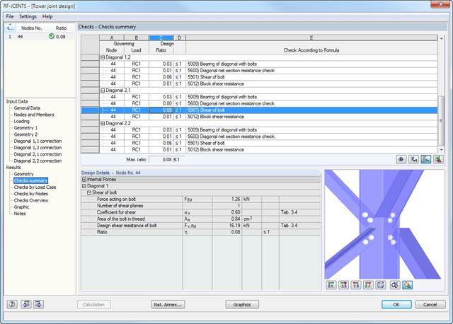
At first, the governing joint designs are arranged in groups and displayed with the basic geometry of the joint in the first result window. In the other result tables, you can see all fundamental design details such as the bearing resistance, shearing, sliding, and others.
Dimensions, material properties, and welds important for the connection construction are displayed immediately and can be printed directly. It is possible to visualize the connections in RF-/JOINTS Steel - Tower or in the RFEM/RSTAB model.
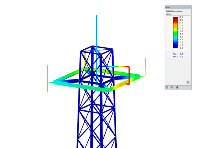
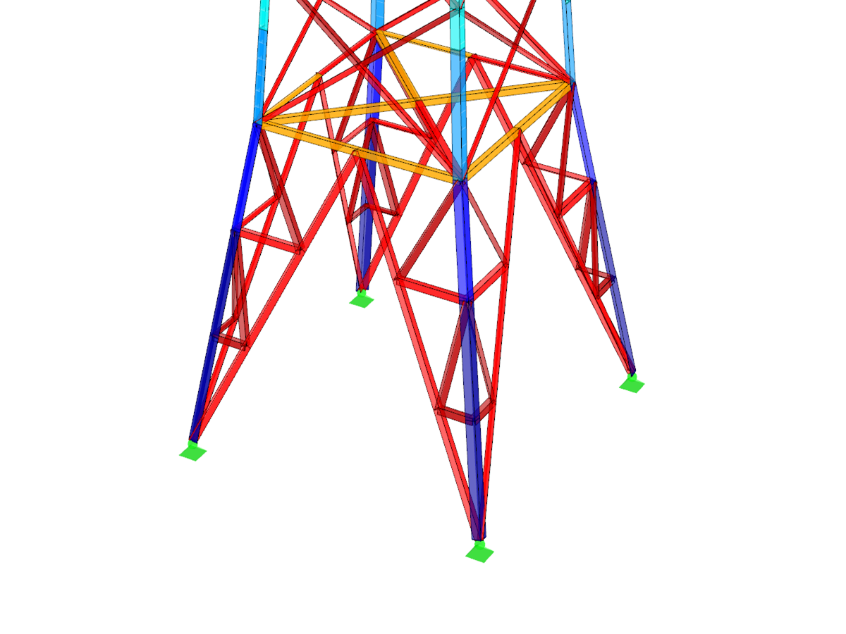
All graphics can be included in the RFEM/RSTAB printout report or printed directly. Due to the scaled output, an optimal visual check is possible as early as in the design phase.
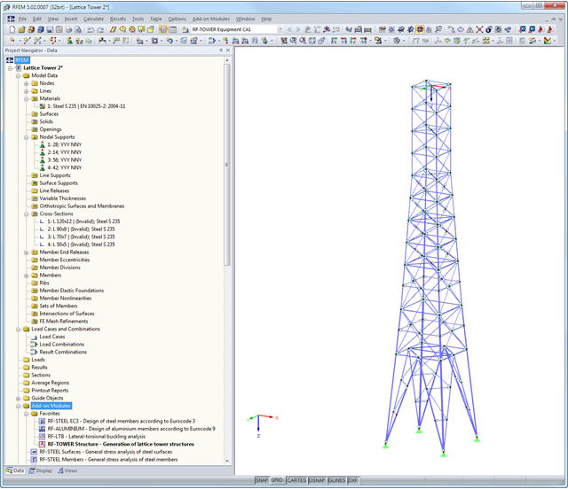
Finally, it is possible to export the generated model to RFEM/RSTAB with a single mouse click.
The complete module data are part of the RFEM/RSTAB printout report. The report contents and the extent of the results can be selected specifically for the individual designs.
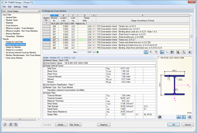
The results are displayed in clearly arranged module windows. In addition to the design data, the results include all design-relevant parameters. A parts list is generated automatically during the calculation.
The complete module data are part of the RFEM/RSTAB printout report. The report contents and the extent of the results can be selected specifically for the individual designs.
When performing the design of tension, compression, bending, and shear loading, the module compares the design values of the maximum load capacity to the design values of the actions. If the components are subjected to both bending and compression, the program performs an interaction. You can determine the factors according to Method 1 (Annex A) or Method 2 (Annex B).
The flexural buckling design requires neither the slenderness nor the elastic critical buckling load of the governing buckling case. The module automatically calculates all required factors for the bending stress design value. RF-/TOWER Design determines the effective critical moment for lateral-torsional buckling for each member on every x-location of the cross-section.
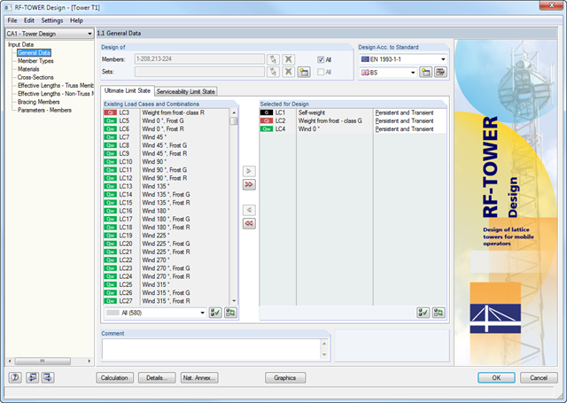
Members of triangular and quadrilateral lattice towers are allocated automatically, provided that the lattice tower was generated in the RF-/TOWER Structure and RF-/TOWER Equipment add-on modules.
However, it is also possible to allocate the members manually. In RF-/TOWER Design, you can use the effective lengths of truss members generated in the RF-/TOWER Effective Lengths add-on module. Manual input is also possible.
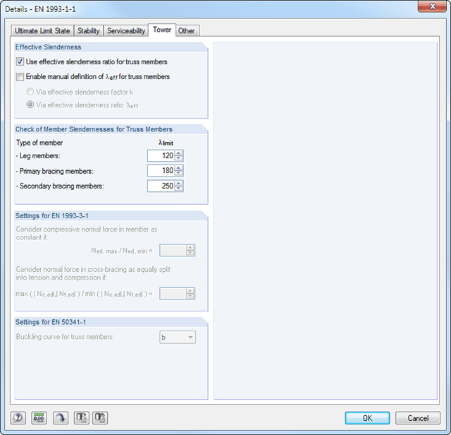
According to the EN 1993-3-1 and EN 50341 standards, different bracing cases and support types can be specified for the leg members and bracing members.
- Consideration of the data from the other RF-/TOWER modules (Structure, Equipment, Loading, Effective Lengths)
- Automatic cross-section classification
- Design of triangular and quadrilateral lattice towers according to EN 1993-1-1, EN 1993-3-1, and EN 50341, including National Annexes
- Flexural buckling analysis of truss members based on the effective slenderness considering bracing and support conditions
- Design of equipment such as platforms according to EN 1993-1-1
- Clearly arranged display of results including relevant parameters in result tables
- Parts list result window
- Creation of a verifiable printout report
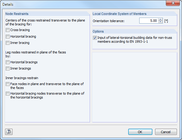
In the Details dialog box, you can specify nodal restraints of the individual bracing types. For example, intersection points of horizontal and vertical bracings can be defined as being kept perpendicular to the bracing plane.
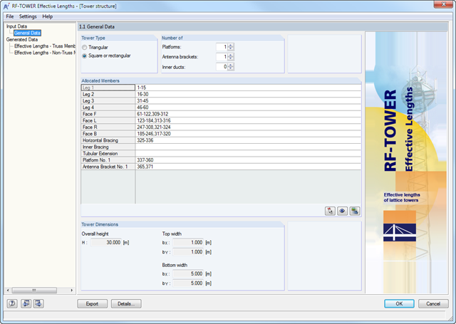
You can specify the tower type, the number of each type of installed equipment, and the allocated members in the individual categories under General Data. The members of lattice towers previously defined in the RF-/TOWER Structure and/or RF-/TOWER Equipment add-on modules are allocated automatically.
Dlubal_KohlA_(2).png?mw=640&hash=ffa4e6b121ede77249a4add96066921e1baf06a9)
- Determination of effective lengths for lattice tower members created in RFEM/RSTAB or RF-/TOWER Structure and RF-/TOWER Equipment
- Options to consider nodal restraints of various bracings
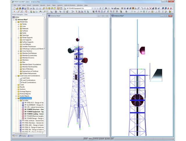
In order to check the overall model graphically, you can use the viewer function. Statically effective equipment can be generated with a single mouse click and exported to RFEM/RSTAB.
All module data are included in the global RFEM/RSTAB printout report.
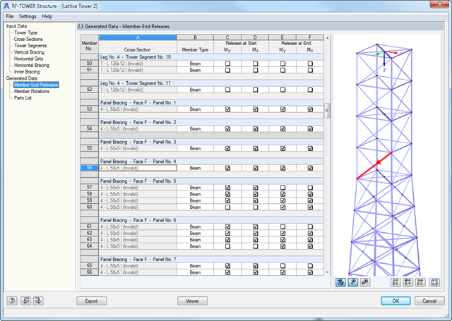
After generating the lattice tower model, the generated data are displayed in clearly arranged tables. The output includes all specifications for member hinges and effective lengths.
In order to check the data graphically, the Viewer function provides a full-screen display, which is also available in the input windows.
First, it is necessary to select a tower type and the relevant materials and cross-sections. The tower geometry is defined by individual tower segments. Slopes can be defined via widths or relatively by geometry modification.
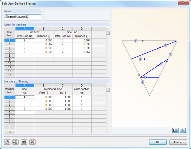
After entering the tower legs, you can specify various stiffening of the lattice tower. It is possible to enter detailed specifications of horizontal girts, inner bracing, and vertical bracing of a tower with unequal sides. An extensive library including parametrized bracing types facilitates the input.
In addition, there is an interactive graphic in all input windows.
After the calculation, RF-/JOINTS Steel - Column Base displays the following design results:
- Net section design
- Bearing resistance design
- Shear
- Block shear resistance
- Sliding
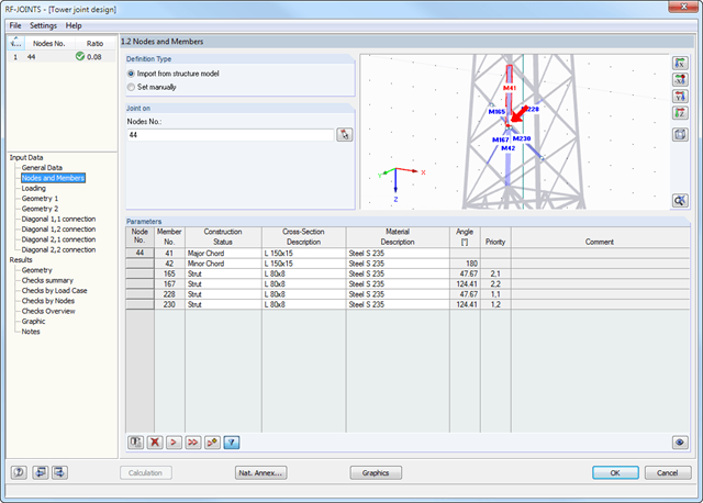
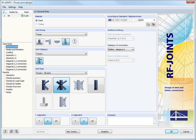
After you have selected the joint type, the connection category, and the design standard in the first input window, you can define the node to be imported from RFEM/RSTAB and to be used for the design of the joint in Window 1.2. Optionally, you can define the connection geometry manually.
In the other input windows, you can then define the parameters of the connection, such as The loading is imported from RFEM/RSTAB or, in the case of manual joint definition, loads are entered.
- Wide range of joint types, for example:
- Bolted connection of diagonals without gusset plate 2D
- Bolted connection of diagonals without gusset plate 3D
- Bolted column joint
- T-, K-, and KT-joints considered for connections of diagonals
- Various categories of connections:
- A - shear/hole bearing connection
- B - slip-resistant connection at serviceability limit state
- C - slip-resistant connection at ultimate limit state
- Bolt strength classes of 4.6 - 10.9
- Bolt diameters M12 - M42
- Modifiable bolt spacing
- Visualization of the entire connection in the view window
.png?mw=640&hash=bfcf1f2df022078fffe5fbe15ce863c80a8534c1)
- Generation of triangular or rectangular tower types
- Access to the extensive material and cross-section library of RFEM/RSTAB
- Simple definition of geometry using tower segments
- Databases for vertical, horizontal, and inner bracing types
- Easy export of generated model data to RFEM/RSTAB
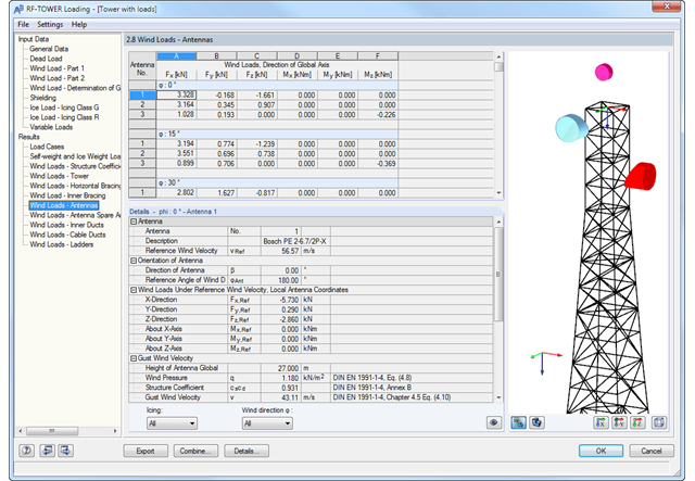
The generated loads can be transferred easily to RFEM/RSTAB in order to superimpose other load cases. All module data is included in the RFEM/RSTAB printout report.
The report contents and the extent of the results can be selected specifically for the individual designs.