
Have you created the entire structure in RFEM? Very well, now you can assign the individual structural components and load cases to the corresponding construction stages. In each construction stage, you can modify release definitions of members and supports, for example.
You can thus model structural modifications, such as those that occur when bridge girders are successively grouted or when columns are settled. Then, assign the load cases created in RFEM to the construction stages as permanent or non-permanent loads.
Did you know that The combinatorics allows you to superimpose the permanent and non-permanent loads in load combinations. In this way, it is possible for you to determine the maximum internal forces of different crane positions or to consider temporary mounting loads available in one construction stage only.
.png?mw=640&hash=688fdfc8af4828c08e9851cddb103a1e86cb899a)
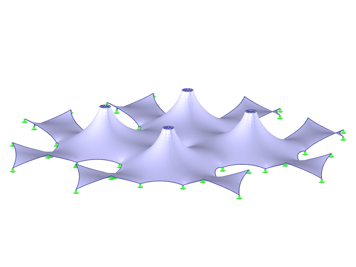
- Form-finding of:
- tension-loaded membrane and cable structures
- compression-loaded shell and beam structures
- mixed tension- and compression-loaded structures
- Consideration of gas chambers between surfaces
- Interaction with supporting structure (substructure design according to various standards)
- Surfaces as a 2D and members as a 1D element
- Definition of different prestress conditions for surfaces (membranes and shells)
- Definition of forces or geometrical requirements for members (cables and beams)
- Consideration of individual loads (self‑weight, inner pressure, and so on) in the form‑finding process
- Temporary support definitions for the form-finding process
- Automatic preliminary form-finding of membrane surfaces (more information...)
- Definition of isotropic or orthotropic material for structural analysis
- Optional definition of free polygon loads
- Transformation of form‑found shape elements into NURBS surface elements
- Possibility of combined form-finding by integration of preliminary form-finding
- Graphical evaluation of the new form using colored coordinates and inclination plots
- Complete documentation of the calculation including user-defined adaptive evaluation figures
- Optional export of the FE mesh as a DXF or Excel file
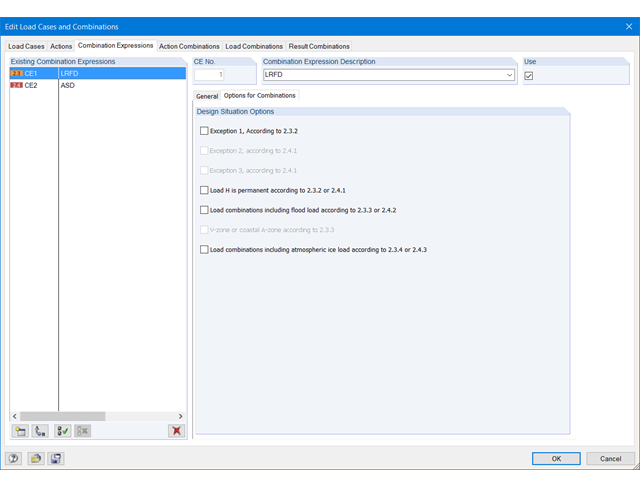
There are three options to reduce the number of combinations. The first two procedures are only available for the generation of load combinations, not for result combinations.
The first option allows for automatic analysis of all load case results (internal forces, deformations, and so on) of selected elements. Then, the program will generate only those combinations that include the load cases producing a maximum or minimum. In addition, you can define a maximum number of relevant load cases, or neglect load cases with a very small contribution to the maximum and minimum values.
The second option allows for automatic evaluation of generated temporary or user-defined result combinations. Then, only the governing load combinations are created.
The third option to reduce the number of generated combinations is to classify only selected actions as leading actions.
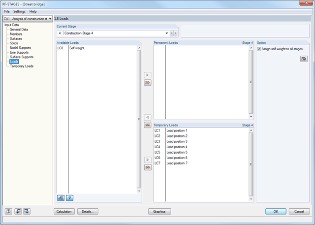
After creating the entire structure in RFEM/RSTAB, the individual structural components as well as load cases and combinations are assigned to the corresponding construction stages. For each construction stage, you can modify for example release definitions of members and supports.
Thus, it is possible to model structural modifications, such as those that occur when bridge girders are successively grouted or when columns are settled. The load cases and load combinations already created in RFEM/RSTAB are divided into "Permanent Loading" and "Temporary Loading" in the add-on module.
The defined temporary loads are superimposed by permanent loads. This way, it is possible to determine the maximum internal forces of different crane positions or to consider temporary mounting loads available only in one construction stage.
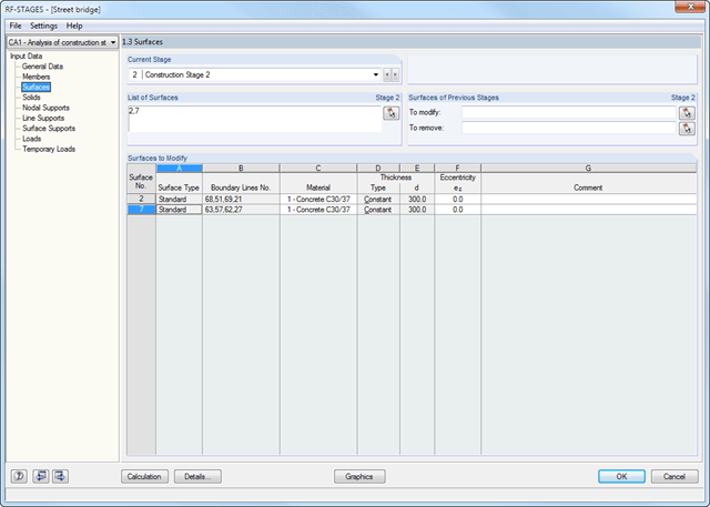
- Simple definition of construction stages in the RFEM/RSTAB structure including visualization
- Addition, removal, and modification of member, surface, and solid properties (such as member hinges, surface eccentricities, degrees of freedom for supports, and others)
- Optional superposition of construction stages with additional temporary loads; for example, mounting loads or mounting cranes, and others
- Consideration of nonlinear effects such as failure of a tension member, elastic foundations, or nonlinear supports
- Numerical and graphical result display for individual construction stages or as an envelope (Max/Min) of all construction stages
- Detailed printout report including all structural and load data of each construction stage