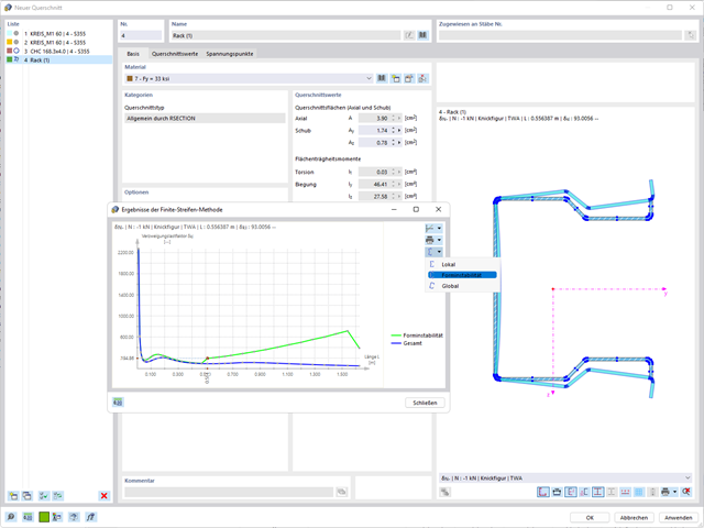
- Available for general thin-walled RSECTION cross-sections
- Classification according to
- EN 1993-1-1
- EN 1993-1-4
- EN 1999-1-1
- Determination of the effective section according to
- EN 1993-1-5
- EN 1993-1-3
- EN 1999-1-1
- Consideration of the effects of distortional buckling of cold-formed sections via eigenvalue method
- Determination of the stresses on the effective section and gross section
- Cross-section, stability, and serviceability limit state design checks of RSECTION cross-sections of Class 4 according to EN 1993‑1‑1 or EN 1999‑1‑1 in the Steel Design or Aluminum Design add-ons
- Cross-section checks for cold-formed RSECTION cross-sections according to EN 1993‑1‑3 in the Steel Design add-on
- Available for all National Annexes integrated in the Steel Design add-on
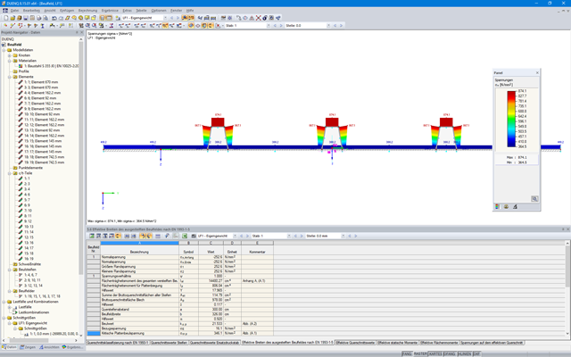
In SHAPE-THIN 8, the effective cross-section of stiffened buckling panels can be calculated according to EN 1993-1-5, Cl. 4.5.
The critical buckling stress is calculated according to EN 1993-1-5, Annex A.1 for buckling panels with at least 3 longitudinal stiffeners, or according to EN 1993-1-5, Annex A.2 for buckling panels with one or two stiffeners in the compression zone. The design for torsional buckling safety is also performed.

- Import of materials, cross-sections, and internal forces from RFEM/RSTAB
- Steel design of thin‑walled cross‑sections according to EN 1993‑1‑1:2005 and EN 1993‑1‑5:2006
- Automatic classification of cross-sections according to EN 1993-1-1:2005 + AC:2009, Cl. 5.5.2, and EN 1993-1-5:2006, Cl. 4.4 (cross-section class 4), with optional determination of effective widths according to Annex E for stresses under fy
- Integration of parameters for the following National Annexes:
-
 DIN EN 1993-1-1/NA:2015-08 (Germany)
 -
 ÖNORM B 1993-1-1:2007-02 (Austria)
 -
 NBN EN 1993-1-1/ANB:2010-12 (Belgium)
 -
 BDS EN 1993-1-1/NA:2008 (Bulgaria)
 -
 DS/EN 1993-1-1 DK NA:2015 (Denmark)
 -
 SFS EN 1993-1-1/NA:2005 (Finland)
 -
 NF EN 1993-1-1/NA:2007-05 (France)
 -
 ELOT EN 1993-1-1 (Greece)
 -
 UNI EN 1993-1-1/NA:2008 (Italy)
 -
 LST EN 1993-1-1/NA:2009-04 (Lithuania)
 -
 UNI EN 1993-1-1/NA:2011-02 (Italy)
 -
 MS EN 1993-1-1/NA:2010 (Malaysia)
 -
 NEN EN 1993-1-1/NA:2011-12 (Netherlands)
 - NS EN 1993-1-1/NA:2008-02 (Norway)
-
 PN EN 1993-1-1/NA:2006-06 (Poland)
 -
 NP EN 1993-1-1/NA:2010-03 (Portugal)
 -
 SR EN 1993-1-1/NB:2008-04 (Romania)
 -
 SS EN 1993-1-1/NA:2011-04 (Sweden)
 -
 SS EN 1993-1-1/NA:2010 (Singapore)
 -
 STN EN 1993-1-1/NA:2007-12 (Slovakia)
 -
 SIST EN 1993-1-1/A101:2006-03 (Slovenia)
 -
 UNE EN 1993-1-1/NA:2013-02 (Spain)
 -
 CSN EN 1993-1-1/NA:2007-05 (Czech Republic)
 -
 BS EN 1993-1-1/NA:2008-12 (the United Kingdom)
 -
 CYS EN 1993-1-1/NA:2009-03 (Cyprus)
 - In addition to the National Annexes (NA) listed above, you can also define a specific NA, applying user‑defined limit values and parameters.
- Automatic calculation of all required factors for the design value of flexural buckling resistance Nb,Rd
- Automatic determination of the ideal elastic critical moment Mcr for each member or set of members on every x-location according to the Eigenvalue Method or by comparing moment diagrams. You only have to define the lateral intermediate supports.
- Design of tapered members, unsymmetric sections or sets of members according to the General Method as described in EN 1993-1-1, Cl. 6.3.4
- In the case of the General Method according to Cl. 6.3.4, optional application of "European lateral-torsional buckling curve" according to Naumes, Strohmann, Ungermann, Sedlacek (Stahlbau 77 [2008], pp. 748‑761)
- Rotational restraints can be taken into account (trapezoidal sheeting and purlins)
- Optional consideration of shear panels (for example, trapezoidal sheeting and bracing)
- RF-/STEEL Warping Torsion module extension (license required) for stability analysis according to the second-order analysis as stress analysis including consideration of the 7th degree of freedom (warping)
- Module extension RF-/STEEL Plasticity (license required) for plastic analysis of cross‑sections according to Partial Internal Forces Method (PIFM) and Simplex Method for general cross‑sections (in connection with the RF‑/STEEL Warping Torsion module extension, it is possible to perform the plastic design according to the second‑order analysis)
- Module extension RF-/STEEL Cold-Formed Sections (license required) for ultimate and serviceability limit state designs for cold-formed steel members according to the EN 1993-1-3 and EN 1993-1-5 standards
- ULS design: Selection of fundamental or accidental design situations for each load case, load combination, or result combination
- SLS design: Selection of characteristic, frequent, or quasi-permanent design situations for each load case, load combination, or result combination
- Tension analysis with definable net cross-section areas for member start and end
- Weld designs of welded cross-sections
- Optional calculation of warp spring for nodal support on sets of members
- Graphic of design ratios on cross-section and in RFEM/RSTAB model
- Determination of governing internal forces
- Filter options for graphical results in RFEM/RSTAB
- Representation of design ratios and cross‑section classes in the rendered view
- Color scales in result windows
- Automatic cross-section optimization
- Transfer of optimized cross-sections to RFEM/RSTAB
- Parts lists and quantity surveying
- Direct data export to MS Excel
- Verifiable printout report
- Possibility to include the temperature curve in the report

- Modeling of the cross-section via elements, sections, arcs, and point elements
- Expansible library of material properties, yield strengths, and limit stresses
- Section properties of open, closed, or non-connected cross-sections
- Ideal section properties of cross-sections consisting of different materials
- Determination of weld stresses in fillet welds
- Stress analysis including design of primary and secondary torsion
- Check of c/t-ratios
- Effective cross-sections according to
- EN 1993-1-5 (including stiffened buckling panels according to Section 4.5)
-
 EN 1993-1-3
 -
EN 1999-1-1
-
to DIN 18800-2
- Classification according to
-
EN 1993-1-1
-
EN 1999-1-1
-
- Interface with MS Excel to import and export tables
- Printout report
.png?mw=640&hash=eaf8e422e9b3dcfb04a920c1d3bf09c1bef0d59a)
General
- Beam to Column joint category: connection possible on the column flange as well as on the column web
- Beam to Beam joint category: optional arrangement of ribs on the opposite side
- Bolt sizes from M12 to M36 with the strength grades 4.6, 5.6, 8.8, and 10.9
- Arbitrary bolt hole spacing and edge distances
- Notching of the beam is possible
- Connection with pure shear loading, pure normal force load (tension joint), or possible combination of normal and shear forces
- Checking compliance with the requirements for pinned joints
- Check of the minimum and maximum bolt hole spacing and edge distances
Web cleat connections
- One or two vertical and up to 10 horizontal bolt rows possible at each leg
- Wide range of equal and unequal angles
- Possible to modify angle orientation
- Designs:
- Shear, bearing resistance, and tension design of bolts
- Shear, bending, and tension design of angles considering deduction of bolt hole
- Shear and tension design of girder web considering deduction of bolt hole
- Tension transmission into the column with the T-stub model
- Notching at the critical section
Fin plate connection
- One or two vertical and up to 10 horizontal bolt rows are possible
- Flexible size of the fin plate
- Location of the fin plate can be modified
- Designs:
- Shear and bearing resistance design of bolts
- Shear, bending, and tension design of fin plates considering deduction of bolt hole
- Stability analysis of long, slender fin plates
- Shear and tension design of girder web considering deduction of bolt hole
- Weld as fillet weld
- Notching at the critical section
End plate connection
- Two or four vertical and up to 10 horizontal bolt rows
- Flexible size of the end plate
- Location of the fin plate can be modified
- Designs:
- Shear, bearing resistance, and tension design of bolts
- Shear and bending design of end plates considering deduction of bolt hole
- Shear and tension design of girder web
- Tension transmission into the column with the T-stub model
- Weld as fillet weld
- Notching at the critical section
End plate connection with cleat
- Fixation of the beam by end plate with two bolts
- Flexible size of cleat and end plate
- Designs:
- Load introduction into the beam according to EN 1993-1-5, Chapter 6
- Support of the stabilizing moment by the bolts and welds at the end plate
- Cleat
- Cleat welds as fillet welds
- Tension transmission into the column with the T-stub model

SHAPE-THIN calculates all relevant cross‑section properties, including plastic limit internal forces. Overlapping areas are set close to reality. If cross-sections consist of different materials, SHAPE‑THIN determines the effective cross‑section properties with respect to the reference material.
In addition to the elastic stress analysis, you can perform the plastic design including interaction of internal forces for any cross‑section shape. The plastic interaction design is carried out according to the Simplex Method. You can select the yield hypothesis according to Tresca or von Mises.
SHAPE-THIN performs a cross-section classification according to EN 1993-1-1 and EN 1999-1-1. For steel cross-sections of cross-section class 4, the program determines effective widths for unstiffened or stiffened buckling panels according to EN 1993-1-1 and EN 1993-1-5. For aluminum cross-sections of cross-section class 4, the program calculates effective thicknesses according to EN 1999-1-1.
Optionally, SHAPE‑THIN checks the limit c/t-values in compliance with the design methods el‑el, el‑pl, or pl‑pl according to DIN 18800. The c/t-zones of elements connected in the same direction are recognized automatically.
- For the design according to Eurocode 3, the following National Annexes are available:
-
DIN EN 1993-1-5/NA:2010-12 (Germany)
-
SFS EN 1993-1-5/NA:2006 (Finland)
-
NBN EN 1993-1-5/NA:2011-03 (Belgium)
-
UNI EN 1993-1-5/NA:2011-02 (Italy)
-
NEN EN 1993-1-5/NA:2011-04 (Netherlands)
-
 NS EN 1993-1-5/NA:2009-06 (Norway)
 -
CSN EN 1993-1-5/NA:2008-07 (Czech Republic)
-
CYS EN 1993-1-5/NA:2009-03 (Cyprus)
-
- In addition to the National Annexes listed above, you can also define a specific NA, applying user-defined limit values and parameters.
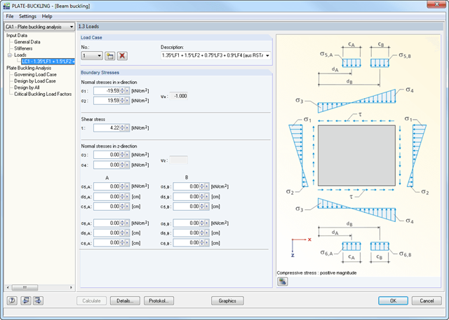
- Import of all relevant internal forces from RFEM/RSTAB by selecting numbers of members and buckling panels with determination of governing boundary stresses
- Summary of stresses in load cases with determination of governing load
- Different materials for stiffener and plate possible
- Import of stiffeners from an extensive library (flat plate and bulb flat steel, angle, T-section, channel, and trapezoidal sheeting)
- Determination of effective widths according to EN 1993-1-5 (Table 4.1 or 4.2) or DIN 18800, Part 3, Eq. (4)
- Optional calculation of critical buckling stresses according to analytical formulas of annexes A.1, A.2, and A.3 of EC 3, or by means of FEA calculation
- Designs (stress, deformation, torsional buckling) of longitudinal and transverse stiffeners
- Optional consideration of buckling effects according to DIN 18800, Part 3, Eq. (13)
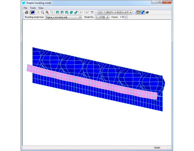
- Photo-realistic representation (3D rendering) of buckling panel, including stiffeners, stress conditions, and buckling modes with animation
- Documentation of all input data and results in a verifiable printout report
The designs are carried out step-by-step by the eigenvalue calculation of the ideal buckling values for the individual stress states, as well as the buckling value for the simultaneous effect of all stress components.
The buckling analysis is based on the method of reduced stresses, comparing the acting stresses to a limit stress condition reduced from the yield condition of von Mises for each buckling panel. The design is based on a single global slenderness ratio determined by the entire stress field. Therefore, the design of single loading and subsequent merging using interaction criterion is omitted.
In order to determine the plate buckling behavior, which is similar to the behavior of a buckling member, the module calculates the eigenvalues of the ideal panel buckling values using freely assumed longitudinal edges. Then, slenderness ratios and reduction factors according to EN 1993-1-5, Ch. 4 or Annex B or DIN 18800, Part 3, Table 1. The design is then performed according to EN 1993-1-5, Chapter. 10 or DIN 18800, Part 3, Eq. (9), (10) or (14).
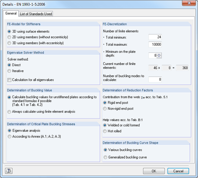
The buckling panel is discretized in finite quadrilateral or, if necessary, triangular elements. Each element node has six degrees of freedom.
The bending component of a triangular element is based on the LYNN-DHILLON element (2nd Conf. Matrix Meth. JAPAN – USA, Tokyo) according to the bending theory of Mindlin. However, the membrane component is based on the BERGAN-FELIPPA element. The quadrilateral elements consist of four triangular elements, while the inner node is eliminated.
The results are displayed with references to EN 1993-1-5 or DIN 18800. In addition, RF-/PLATE-BUCKLING shows calculation results separately for the action of only one edge load as well as for the simultaneous effect of all edge loads.
In the case of several load cases, the governing load case is displayed separately. Thus, time-consuming comparison of calculation data is not necessary.
Window 2.5 lists the critical buckling load factors of all load cases and the respective buckling modes.
You can visualize the buckling modes and loads of the buckling panel in the graphic window. This facilitates a quick overview of the buckling modes and loads. Using the animation option, you can clearly represent the buckling behavior of stiffened plates.
Finally, it is possible to export all tables to MS Excel or in a CSV file.